
3D Printing Prototypes for Consumer Electronics: Design Tips
High-quality 3D printed consumer electronics prototypes serve as the backbone of modern hardware development, allowing teams to validate complex internal assemblies and external aesthetics simultaneously. By moving from a digital CAD file to a physical object in hours, engineers can identify ergonomic flaws and mechanical interference issues that are impossible to spot on a 2D screen. This speed is essential for maintaining a competitive edge in an industry where product lifecycles are measured in months rather than years.
Why are 3D Printed Consumer Electronics Prototypes Necessary?
A 3D printed consumer electronics prototypes workflow is necessary because it minimizes the risk of multi-thousand-dollar tooling errors and accelerates the time-to-market. These physical models allow designers to test real-world ergonomics, verify the fit of delicate internal components like PCBs, and conduct user-experience testing with a tactile device before committing to mass production.
In my years of consulting for hardware startups, the most common pitfall is over-reliance on digital simulations. I recall a project for a handheld gaming peripheral where the CAD model passed every stress test. However, once we produced the 3d printing prototype, we realized the trigger buttons felt "mushy" because the internal support ribbing was too thin for human tactile feedback. We redesigned the internal geometry and had a second, perfect prototype within 24 hours. Without that physical check, the client would have spent [data: ~15-20k] on a steel mold that didn't work.
What are the Best Design Tips for Electronics Prototypes?
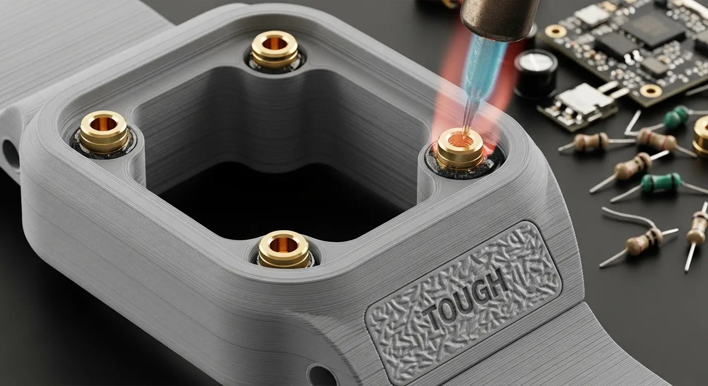
The best design tips for electronics prototypes include prioritizing wall thickness for structural integrity, designing internal screw bosses for thermal inserts, and orienting parts to minimize support structure marks on visible surfaces. Additionally, designers should incorporate tolerances of at least 0.1mm to 0.2mm between mating parts to account for material shrinkage and ensure a perfect snap-fit or sliding assembly.
| Design Feature | Recommended Practice | Why It Matters |
| Wall Thickness | Minimum 1.5mm for most resins | Prevents warping and ensures durability |
| Screw Bosses | Use heat-set inserts instead of raw threads | Provides stronger, reusable mechanical connections |
| Tolerances | 0.15mm gap for interlocking parts | Accounts for printer accuracy and resin expansion |
| Draft Angles | Not strictly required for 3D printing | Prepares the design for low-volume injection molding |
| Fillets/Radii | Avoid sharp 90-degree internal corners | Reduces stress concentrations and prevents cracking |
How should you handle internal component fit?
When designing for 3D printed consumer electronics prototypes, always leave "breathing room" for your electronics. PCBs are rarely perfectly flat, and cables take up more space than you think. I always suggest a 0.5mm offset around the perimeter of the board. This ensures that even if there is slight material warping, the board won't be under mechanical stress when the enclosure is screwed shut.
Why is part orientation critical for aesthetics?
For consumer devices, "A-side" surfaces must be flawless. When you send a file to Top 10 Rapid Prototyping Manufacturers, specify that support structures should only be placed on internal or hidden faces. This prevents the "pitting" effect that occurs when supports are snapped off, saving hours of manual sanding and post-processing time.
Which Materials Best Simulate Production Plastics?
The best materials for electronics prototypes are "Tough" or "Durable" resins that mimic ABS or Polycarbonate, and Nylon (PA12) for functional mechanical parts. For devices requiring soft-touch grips or gaskets, flexible elastomers like TPU (Thermoplastic Polyurethane) are used to simulate the feel of overmolded rubber often found on high-end consumer tech.
Simulating ABS and Polycarbonate (PC)
Most consumer electronics use ABS for its impact resistance. In the 3D printing world, SLA "Tough" resins are engineered to have similar elongation-at-break properties. If your device needs to survive a "drop test" from table height, using a standard, brittle resin will give you a false failure. Always select a material that matches the modulus of your final production plastic.
Using Multi-Material Printing for "Overmolding"
Modern Top 20 Rapid Prototyping Manufacturers offer PolyJet or Multi-Jet Fusion technology. This allows you to print a rigid shell and a soft rubberized grip as a single part. This is a game-changer for testing the "feel" of a power tool handle or a wearable device without needing a complex multi-stage molding process.
How do you Test Functional Prototypes for Electronics?
Testing functional prototypes involves verifying the assembly workflow, checking for thermal hotspots, and performing signal interference tests. Engineers physically install all internal hardware into the 3D printed shell to ensure that buttons actuate correctly, light pipes distribute LED light evenly, and the device can be easily serviced or disassembled for repairs.
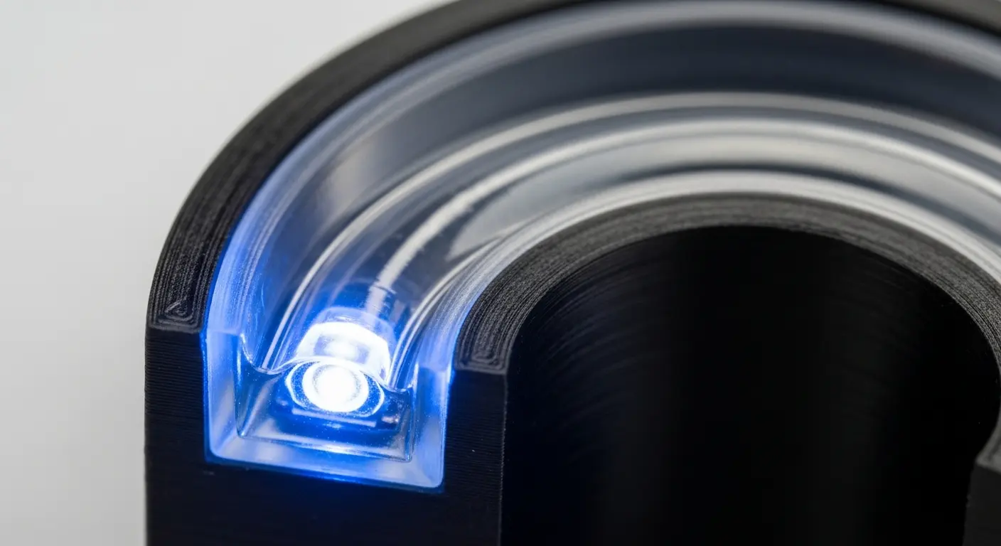
Tip: If your device has internal LEDs, use a "Clear" SLA resin for your light pipe prototypes. To avoid light leakage, paint the sides of the light pipe black, leaving only the entry and exit points clear. This perfectly mimics production-grade light pipe performance.
Checking for Thermal and RF Issues
Consumer electronics generate heat and emit signals. Some 3D printing materials can act as insulators, trapping heat and potentially damaging your PCB during a long-run test. Similarly, certain carbon-filled materials can block Wi-Fi or Bluetooth signals. Always perform a 4-hour "burn-in" test with your prototype to ensure the enclosure doesn't deform under the operating temperature of the electronics.
How to Transition from 3D Printing to Mass Production?
Transitioning involves refining the 3D design to be "molding-friendly" by adding draft angles, consistent wall thicknesses, and ejector pin locations. During the final stages of 3D printed consumer electronics prototypes development, many companies bridge the gap using molding vs. 3d printing analysis to decide if a "bridge tool" is needed before high-volume manufacturing.
The Role of Bridge Tooling
If you need 100-500 units for "Beta" testing, 3D printing can become expensive and slow. This is where low-volume injection molding comes in. You use the data from your 3D prints to create a simplified aluminum mold. This gives you parts in production-grade materials at a fraction of the cost of a full production steel tool, allowing for final certification testing (UL, CE, FCC) with parts that are identical to the mass-market version.
Finalizing the "Bill of Materials" (BOM)
Your 3D prototype helps finalize your BOM. It tells you exactly how many screws you need, the length of your internal wiring, and whether you need adhesive gaskets. By the time you reach mass production, there should be zero "surprises" in your assembly line costs.
What are the Common Mistakes in Electronics Prototyping?
Common mistakes include ignoring material shrinkage, failing to account for the thickness of surface finishes (like paint or chrome plating), and designing screw bosses that are too thin to support mechanical loads. Furthermore, many designers forget to include "cable management" features, leading to pinched wires during the final assembly of the prototype.
- Ignoring Finish Thickness: A layer of professional paint can add 0.1mm to 0.2mm to a surface. If your tolerances are too tight, the painted parts won't fit together.
- Underestimating Shrinkage: Large, flat 3D printed parts tend to "curl" at the edges. Using ribs or "honeycomb" internal structures can help maintain flatness.
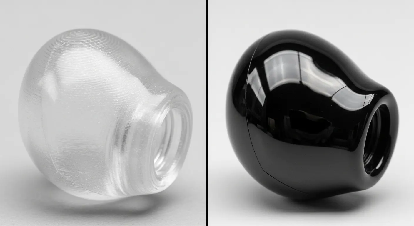
- Poor Light Pipe Design: If a light pipe isn't polished to a high gloss, the light will appear dim and diffused rather than crisp.
Future Trends: 3D Printed Electronics and Smart Materials
The next frontier of 3D printed consumer electronics prototypes is the integration of conductive traces directly into the 3D print. Using specialized "Aerosol Jet" or "Voxel" printing, we can now embed antennas and simple circuits directly into the plastic enclosure. This reduces the footprint of the device and allows for radical new form factors that are not limited by flat, rectangular PCBs.
We are also seeing the emergence of "Shape Memory" polymers. These materials can change their shape when an electric current is applied, potentially allowing for "active" ergonomics or devices that physically expand and contract based on user needs.
Designing for Success in Consumer Tech
To ensure your 3D printed consumer electronics prototypes are successful, you must view the prototype not just as a model, but as a "test bed."
- Modular Design: Design your prototype in sections so you can swap out a button panel without reprinting the entire enclosure.
- Post-Processing Readiness: If you plan to paint the part, ensure the 3D material is compatible with primers and doesn't "outgas," which can cause bubbles in the paint.
- Labeling: Print part numbers or revision dates directly into the internal faces of your 3D parts to keep track of iterations.
Final Thought
The success of 3D printed consumer electronics prototypes lies in their ability to fail early and cheaply. By following these design tips—from managing tolerances to selecting the right engineering-grade resins—you transform a simple 3D print into a powerful diagnostic tool. As the line between prototyping and production continues to blur, the teams that master the "digital-to-physical" workflow will be the ones that define the next generation of consumer technology. Whether you are building a simple remote or a complex wearable, the prototype is your roadmap to a flawless product launch.