


What Tolerance are Required in Aerospace Precision CNC Machining?
Aerospace parts are often described as "high precision," but there is no single tolerance for every bracket, housing, shaft, connector, or flight-test component. In Aerospace Precision CNC Machining, accuracy depends on function, material, size, assembly conditions, operating temperature, and inspection method.
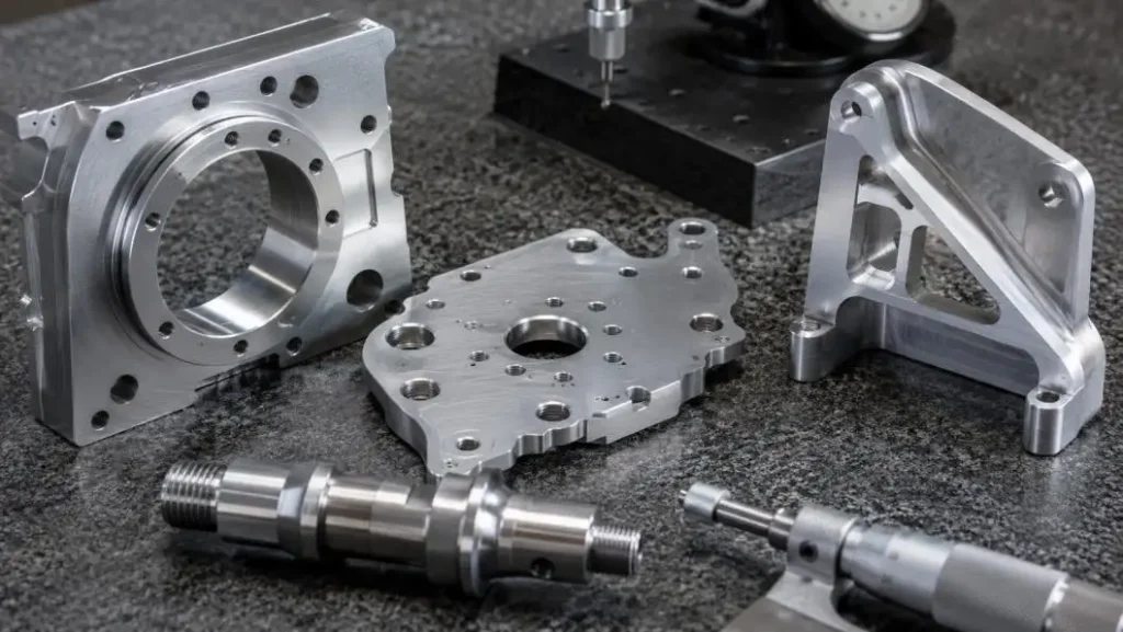
A non-critical cover may accept broad limits, while a bearing seat, sealing surface, sensor interface, or aligned hole pattern may need control within a few micrometers. The goal is not to specify the tightest tolerance everywhere. It is to control the features that influence fit, sealing, motion, load transfer, thermal management, and reliability.
What is CNC Machining Tolerance?
Tolerance designates the maximum and minimum limits of acceptable measurement deviations. For example, if a specified diameter must be 20.000 mm, and we assume a machining tolerance of ±0.010 mm, the diameter could be 19.990 mm at the minimum and 20.010 mm at the maximum.
Precision in Aerospace Engineering includes geometrical consideration as well.
•Form Tolerance: Variation in the forms of straightness, flatness, circularity and cylindricity.
•Orientation Tolerance: Relationships among features in tolerances of parallelism, perpendicularity and angularity.
•Location Tolerance: Position and profile controls of holes and surfaces.
•Datum Structure: The intended assembly relationship in manufacturing and inspection is defined by the functional datums.
ASME Y14.5 is the leading standard for Geometric Dimensioning and Tolerancing (GD&T), which is the most accepted framework for communicating tolerances to designers, CNC (computer numerical control) programmers, machinists and inspectors.
What Level of Precision is Required for Aerospace Parts?
General CNC (computer numerical control) tolerances are often in the range of ±0.10 to ±0.05 mm. However, features in Aerospace Engineering may require tolerances up to ±0.01 mm, ±0.005 mm or tighter. These are illustrative ranges rather than universal aerospace rules.
| Feature Type | Illustrative Tolerance | Functional Purpose |
| Covers and guards | ±0.10 to ±0.05 mm | General fit |
| Structural brackets | ±0.05 to ±0.02 mm | Alignment and load transfer |
| Hole patterns | ±0.02 to ±0.01 mm | Repeatable assembly |
| Bearing seats and bores | ±0.01 to ±0.005 mm | Controlled fit and motion |
| Sensor interfaces | Feature-specific | Stable positioning |
The same numerical tolerance can present different manufacturing challenges. Maintaining ±0.005 mm on a short steel bore is not equivalent to holding it across a large, thin-wall aluminum housing.
Feature size, rigidity, material, coating thickness, datum selection, and measurement uncertainty must therefore be reviewed together.
Why Are Aerospace Tolerances Function-Driven?
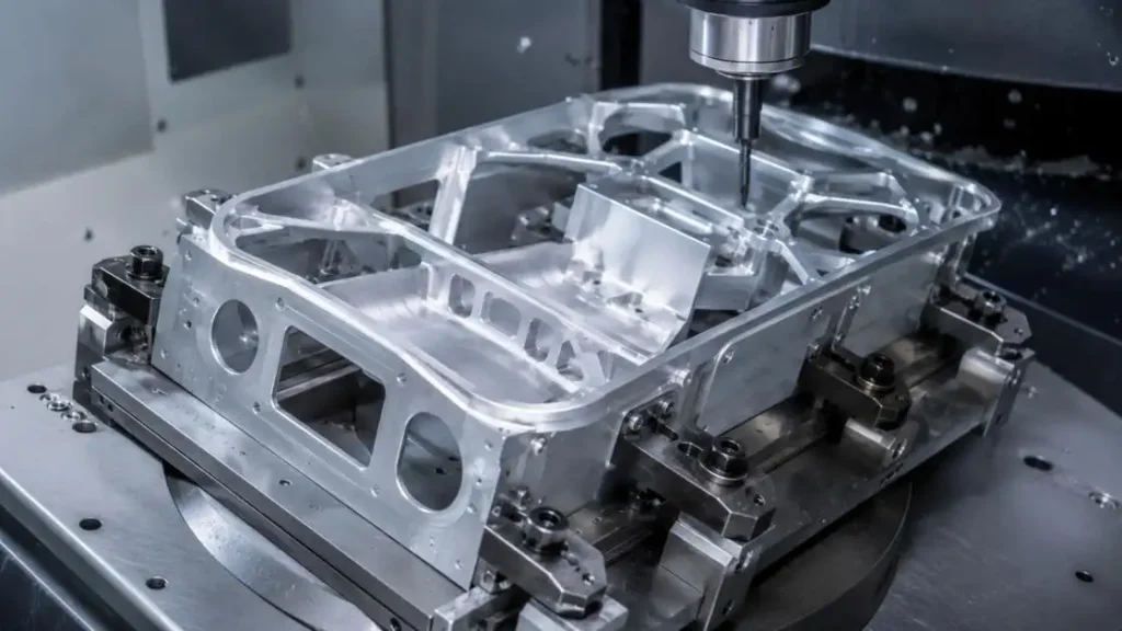
Aerospace Precision CNC Machining services the machining needs of avionics, unmanned aerial vehicles, satellites, battery modules, cabin electronics, thermal systems and flight-test equipment.
Each of the above applications has unique requirements around dimensional accuracy.
•Avionics Housings: Precision in Connector placement, wall thickness and sealing grooves is necessary for optimal packing of the avionics and ensuring environmental protection.
•UAV Structures: Machining distortion is a concern when utilizing lightweight pockets and thin, wall designs.
•Satellite Components: For assembly, positioning and alignment of satellite systems, interfaces with a high degree of control are necessary.
•Power Modules: Performance of fastening, electrical insulation, and thermal conduction is improved with a high degree of flatness in the mounting surface.
•Sensor Housings: The position of a sensor relative to a surface is critical in determining the sensor's measurement repeatability, thus requiring a stable surface.
Aerospace tolerances should therefore be connected to a functional requirement. Tight control may be necessary for a mounting surface, while a nearby non-contact surface may use a broader tolerance.
What Makes Tight Tolerances Difficult?
The final accuracy of a product is determined by the totality of the production system, not the accuracy claims of the CNC machinery.
•Thermal Expansion: Changes in the ambient temperature of the machinery, tooling, components, and even measuring devices, will lead to expansion or contraction.
•Material Behavior: Each of the materials listed - aluminum, titanium, stainless steel, PEEK, and nylon - will react differently when subjected to the conditions of machining.
•Thin-Wall Distortion: Low density structures may either bend or relax after being removed from the fixture (post machining).
•Tool Deflection: Cutting loads may change the final shape if the tool is either too long or has too small a diameter.
•Fixture Strategy: The wrong choice of datums or too much clamping may lead to the same errors in deformation and lack of repeatability.
•Tolerance Stacking: Even if the individual components of an assembly meet the required specifications, the assembly may still fail to function.
Dimensional measurements are commonly referenced to 20°C because temperature changes can affect both the workpiece and the measurement result.
For this reason, precision aerospace components may need sufficient stabilization time before final measurement.
How Are Aerospace CNC Parts Inspected?
Inspection planning, particularly for drawings involving complex GD&T, should always precede machining.
•CMM Inspection: A coordinate measuring machine measures and evaluates the size, position, profile, flatness, and alignment with datum features.
•Micrometers and Bore Gauges: These instruments measure both external diameters and lengths which can be reached. Also, measure the exact internal diameters of small bores.
•Surface Testing: Measuring the average roughness to evaluate conformity of the machined features to the required Ra by using a roughness measuring instrument or profilometer.
•First article Inspection: This is the formal review of the first part produced to ensure that the proposed method of manufacture and the method of inspection will fulfill the drawing requirements.
•In-Process Checks: Measuring tools used to check the dimensions of features between operations will identify thermal drift and setup variation, as well as changes in dimensions, prior to completing final machining operations.
Inspection equipment should be selected according to the feature being measured. A standard caliper may be suitable for a general outside dimension but may not provide enough resolution for a precision bearing seat or tightly controlled hole position.
The aerospace 9100 quality-management standard builds on ISO 9001 and adds aviation, space, and defense requirements involving risk, documentation, configuration, traceability, and supply-chain control.
SunOn's Design and Technical Approach
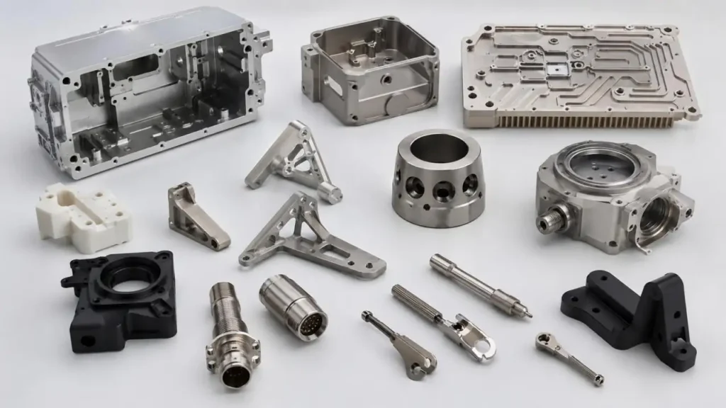
SunOn provides Aerospace Precision CNC Machining for lightweight, high-reliability metal and engineering-plastic components used in UAVs, avionics, satellites, thermal systems, and flight-test equipment.
| Technical Capability | SunOn’s Data |
| Dimensional Tolerance | ±0.10 mm to ±0.002 mm |
| Surface Finish | Down to Ra 0.8 μm |
| Machining Technology | 3-axis, 4-axis, and 5-axis CNC |
| Prototype Lead Time | As fast as 72 hours |
| Production Volume | From 1 to 100 pieces for low-volume projects |
| Materials | Aluminum, titanium, stainless steel, PEEK, nylon, and brass |
| Inspection | CMM, micrometers, calipers, and bore gauges |
SunOn's ±0.002 mm capability applies only to some selected critical features and under controlled conditions during machining and inspection. It does not mean that precision at this level is achievable for all features of a given part.
•DFM Review: Engineers examine deformations, tolerances, wall thickness, and the selection of datums.
•Five-Axis Machining: Machining of complex geometries and angles can be done in a few set ups.
•Process Control: Measurement and contingency methods for tool wear, machining forces, and the effects of different sequences of operations and variable temperatures, can be applied.
•Quality Inspection: Measurement and verification of GD&T along with the required surface finish are done and certified before the parts are shipped.
SunOn's expertise related to the design and manufacture of molds for the aerospace industry includes:
•Lightweight Packaging: Molds can be manufactured to create lightweight housings with controlled wall thickness.
•Sensors: Molds can be manufactured to allow the positioning of internal components with cavities and precise features.
•Structures: Molds can be designed for various features and geometries which can accommodate spacing and the positioning of elements.
•Shields: Molds can be designed to assist in the production of components with flowing and changing materials.
•Housings: Molds can be designed to aid in the production of components with highly spaced and small features.
SunOn can design molds that allow the integration of flow materials and cooling features to assist in the control of dimensional accuracy.
SunOn offers prototyping, precision machining, fabrication of molds and dies, and assembly services to the aerospace and automotive industries. SunOn is certified with ISO 9001, ISO 14001, and IATF 16949.
Final Takeaway
The correct aerospace tolerance protects function, reliability, and assembly while remaining practical to manufacture and verify.
Aerospace Precision CNC Machining can achieve tight dimensional control, but successful results depend on coordinated decisions involving GD&T, material behavior, thermal effects, fixturing, machining sequence, surface finishing, and inspection.
Send us your 2D drawings or 3D models to receive a DFM review, manufacturing recommendation, and project quotation.
FAQs
Q1: How is Inspection done on Aerospace CNC parts?
Inspection is done quite easily with the use of CMMs, micrometers, bore gauges, and surface testers.
Q2: What is the best achievable tolerance for aerospace CNC parts?
Aerospace CNC Machining can achieve tolerances of ±0.002 mm in features.
Q3: What materials do you typically machine?
Machinable materials include aluminum, titanium, stainless steel, PEEK, nylon, and other available engineering materials.
Q4: Why is 5-axis CNC used for aerospace parts?
Reduced error and less setups are required for 5-axis CNC Machining as it allows high precision for complex part designs.
Q5: What affects the precision of part design in CNC Machining?
Several elements affect precision such as the material being machined, design geometry, temperature, and quality of tools, fixtures, and inspection methods.
