


Components of an Injection Mold: Full Guide for Manufacturing Pros
Injection molding is one of the most widely used manufacturing processes for producing high‑precision, high‑volume plastic parts. At the heart of this process lies the injection mold tooling, a carefully engineered system composed of many interdependent parts. These components work in harmony to guide molten plastic, shape it into the desired geometry, cool it down, and eject the finished product. A deeper understanding of the components of an injection mold helps engineers optimize mold design, improve part quality, and reduce production issues.
What Is an Injection Mold?
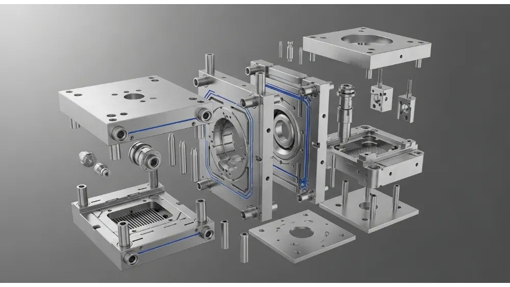
An injection mold is a precision‑machined metal tool that defines the shape of the plastic part. It consists of two major halves—one fixed and one movable—that come together to form a cavity (the negative shape of the final part) when closed. Molten plastic injected under high pressure flows through a system of channels to fill the mold and solidify into a finished part. The entire system includes structural components, feeding systems, temperature control mechanisms, moving parts, and auxiliary features.
Core Mold Halves: Stationary and Moving Sections
The basic structure of any injection mold consists of two complementary halves:
Stationary Side (Cavity A Side)
This half remains fixed to the molding machine’s stationary platen. It typically holds the cavity plate, runner system entry points, and cooling lines. Its function is to define the external shape of the plastic part and provide the foundation for molten plastic entry. Guide pins and bushings ensure precise alignment with the opposite half.
Moving Side (Cavity B Side)
The moving half attaches to the machine’s movable platen and carries components such as ejector mechanisms and core inserts. During mold open/close cycles, this side moves toward the stationary half to form the complete mold cavity. It also supports the ejection of finished parts after cooling.
Runner and Gate Systems
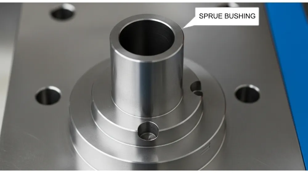
Once plastic is melted and pressurized inside the barrel, it must be transported into the mold cavity through a guided network of paths known as the runner system. The main sections include:
- Sprue Bushing: Connects the machine nozzle to the runner.
- Runner Network: Channels that split and deliver plastic to multiple cavities in multi‑cavity molds.
- Gate: The smallest opening where plastic enters the cavity. Gates can be edge, pin, fan, or other styles depending on flow requirements.
Runners are typically designed as either cold runners, which carry plastic without heating, or hot runners, which keep the plastic molten until it reaches the gate.
Cooling System: Temperature Control Backbone
The cooling system often accounts for the majority of cycle time in injection molding. Without efficient cooling, parts can warp, sink, or exhibit poor dimensional accuracy. The cooling system typically includes:
- Cooling Channels: Drilled or conformal paths around the mold cavity to circulate coolant.
- Baffles & Bubblers: Help direct coolant to specific regions for uniform heat removal.
- Thermal Pins: Hollow pins that improve heat transfer in targeted areas.
- External Pumps: Maintain coolant flow and pressure.
Effective cooling increases production efficiency, reduces cycle times, and minimizes defects such as warpage or sink marks.
Shaping Components: Cores, Cavities, Pins
These are the elements that directly form the geometry of the molded part:
- Mold Cavity: Defines the outer profile of the finished product.
- Core: Creates internal geometry, such as holes or hollow sections.
- Core Pins / Molding Rods: Produce narrow features or details inside the part.
- Lifters: Support angled features and undercuts, ensuring easy ejection.
These elements must be machined to high tolerances, as they determine the part’s final dimensional accuracy and surface finish.
Venting System: Promoting Clean Fill and Quality
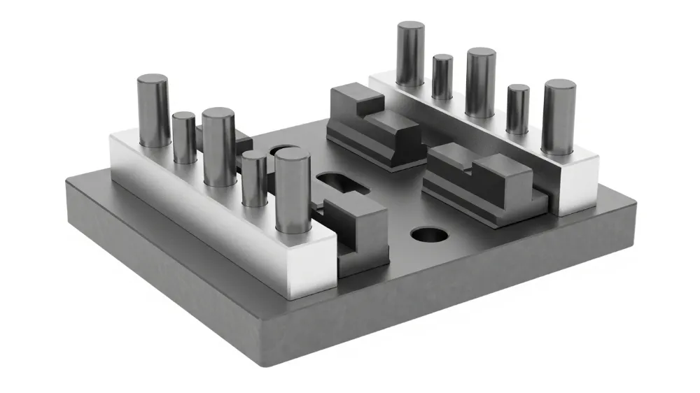
During injection, air can become trapped inside the cavity, leading to voids, burn marks, or incomplete fill. A venting system provides escape paths for trapped air. Elements of venting include:
- Venting Grooves: Fine channels along the parting line.
- Vacuum Systems: External pumps that pull air out before injection begins.
- Micro‑Vent Valves: Precise valves that regulate air flow without plastic leakage.
Well‑designed venting reduces defects and helps achieve consistent part quality.
Guiding and Alignment Systems
Precision alignment of mold halves is crucial to prevent flash and ensure consistent cycle performance. The guiding system includes:
- Guide Pins & Bushes: Ensure both halves align precisely during closure.
- Support Plates: Maintain structural rigidity during repeated cycles.
Without proper guiding, molds can shift, increasing wear and reducing part accuracy.
Ejector System: Safe Part Removal
After cooling, the part must be gently and consistently removed from the mold. The ejector system consists of:
- Ejector Pins: Thin rods that push the part out of the cavity.
- Ejector Plates & Sleeves: Support and transmit ejection force.
- Return Pins: Help reset the ejector assembly for the next cycle.
Well‑designed ejection prevents damage to delicate features and ensures smooth production.
Mold Base and Auxiliary Components
The mold base is the structural foundation that holds all functional systems. Key elements include:
- Clamp Plates: Secure the mold to the injection machine.
- Locating Rings: Ensure correct positioning relative to the nozzle.
- Support Pillars: Maintain spacing and distribute clamping forces.
Auxiliary parts like sprue bushings, material grabbers, and retainer pins support overall performance and durability.
Special Mechanisms for Complex Parts
For advanced part geometries, injection molds may include:
- Slides and Side Actions: For undercuts and lateral features.
- Hydraulic Cylinders: To actuate complex moves during molding.
- Dead Corner Handling: Tools to fill and release hard‑to‑reach features.
Common Mold Defects and Prevention
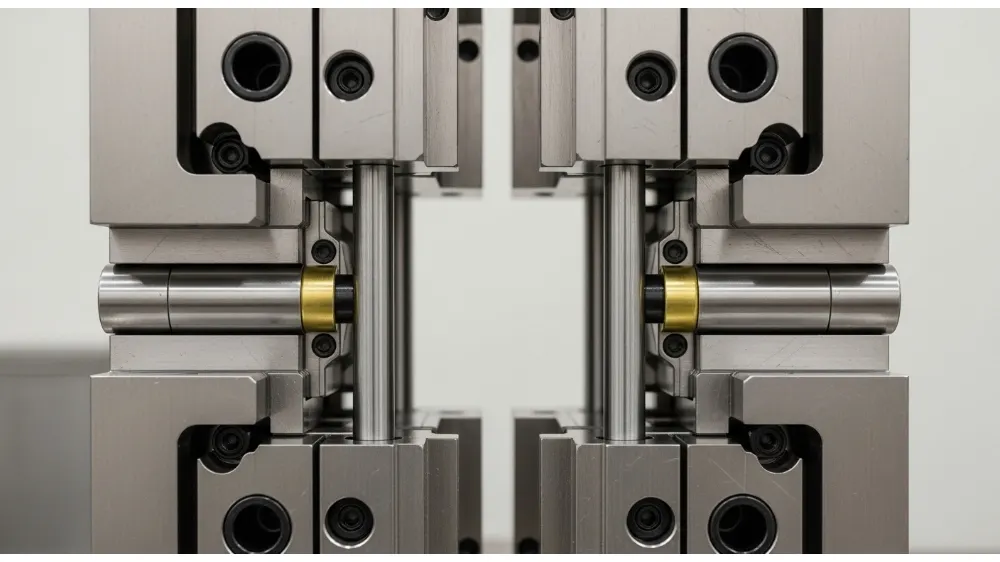
Even with a well‑designed mold, issues can arise. Some common problems include flash, incomplete fill, cooling channel blockages, and ejection marks. These can be mitigated by:
- Adjusting runner and gate design
- Improving coolant circulation and venting
- Optimizing ejector pin size and placement
- Enhancing surface finish and draft angles
Understanding how components of an injection mold affect production helps engineers proactively prevent defects.
Materials Used for Injection Molds
Mold materials vary depending on production volume, plastic type, and precision requirements. Common choices include:
- Tool & Stainless Steels: High durability for long runs.
- Aluminum Alloys: Lower cost for prototype or low‑volume runs.
- Beryllium Copper: Excellent thermal conductivity for specific components.
Each material affects durability, cycle time, and cost differently.
FAQ – Common Questions About Injection Mold Components
Q1: What are the main functions of an injection mold?
A: It shapes molten plastic into finished parts by guiding material flow, controlling temperature, and enabling part ejection.
Q2: What is the runner system?
A: The runner system comprises channels like the sprue, runners, and gates that direct molten plastic from the nozzle into cavities.
Q3: Why is cooling important in injection molds?
A: Proper cooling reduces cycle time, prevents warpage, and improves dimensional accuracy.
Q4: What materials are best for mold manufacturing?
A: Tool steels and stainless steels are ideal for long‑life molds; aluminum suits rapid tooling and prototypes.
Q5: How do vents enhance part quality?
A: Vents allow trapped air to escape, preventing voids and incomplete filling.
Conclusion
The components of an injection mold are more than just parts—they are precision instruments that influence product quality, cycle time, and overall manufacturing success. By understanding each system—from runners and cooling channels to ejectors and auxiliary hardware—engineers can design molds that deliver efficient, reliable, and high‑quality results. Choosing the right materials, optimizing component design, and anticipating potential defects are key factors in achieving excellence in injection molding.
