
Engineering Drawing Tips: Comprehensive Guide for Precision Design & Manufacturing
Engineering drawings are the backbone of product design and manufacturing. They communicate geometry, dimensions, tolerances, and assembly instructions that turn concepts into physical parts. Whether you’re preparing drawings for machined parts, sheet metal fabrication, or complex assemblies, precision and clarity are crucial. Without them, confusion in production, costly rework, and part failures can quickly follow.
This guide offers practical engineering drawing tips that help designers, drafters, and engineers produce accurate, standardized, easy‑to‑interpret drawings. You’ll learn how to improve legibility, avoid common errors, apply standards, and shorten the time from design to production—all while minimizing costly misinterpretations.
Understand the Purpose of the Drawing
Before you start drafting, define why the drawing exists. Is it for fabrication, inspection, or assembly? Knowing the purpose determines the level of detail required. Machinists typically need full dimensions and tolerances. Quality inspectors may need geometric tolerances and datum references. Assembly teams might focus more on exploded views and fit notes.
The clearer the intent, the more useful the drawing. Think of your drawing as a communication tool—every line, annotation, and symbol should convey information, not ambiguity.
Use Standardized Views and Projection Methods
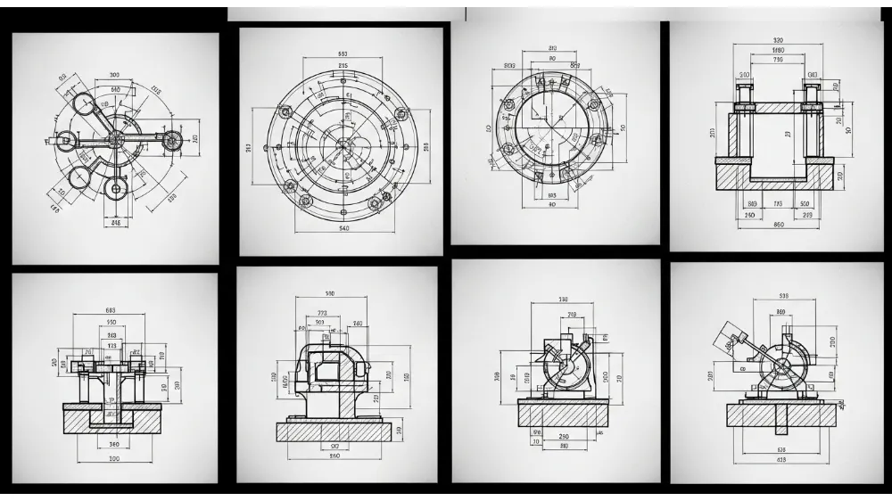
Consistent use of projection methods—such as first‑angle or third‑angle projection—is essential, especially when collaborating across teams or with external partners. Use standard orthographic views (front, top, side) and include additional section views when needed.
Adding auxiliary views for inclined surfaces or detail views for intricate features helps prevent misinterpretation. Label each view clearly to reduce confusion.
Internal link suggestion: Link “orthographic views” to a Yanmee page on CAD design services or drafting standards.
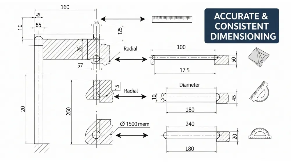
Prioritize Clear Dimensioning
Dimensions are the heart of engineering drawings. They must be complete yet concise. Follow these dimensioning principles:
- Place dimensions outside the object where possible.
- Avoid redundant or conflicting dimensions.
- Use extension lines that clearly connect features to their values.
- Maintain consistent spacing and alignment for readability.
When dimensioning complex parts, prioritize features that control function first (e.g., critical hole locations, mating surfaces) and secondary features last.
Internal link suggestion: Link “critical hole locations” to a Yanmee article about manufacturing drilling and tolerancing.
Apply Geometric Tolerances Correctly
Geometric Dimensioning and Tolerancing (GD&T) goes beyond basic linear tolerances and controls form, orientation, location, and profile. Applying GD&T symbols where appropriate can dramatically reduce ambiguity in production and inspection.
For example, instead of specifying multiple linear tolerances for a hole pattern, a position tolerance with a datum reference frame can ensure the entire pattern meets assembly requirements.
Keep your GD&T consistent and always reference the latest standards (e.g., ASME Y14.5). When in doubt, consult with manufacturing or quality teams to ensure interpretations align.
Internal link suggestion: Link “GD&T symbols” to a Yanmee resource on geometric tolerancing best practices.
Include Material and Finish Specifications
Materials affect manufacturability, surface quality, and performance. Always specify the base material, heat treatment (if any), surface finish requirements (e.g., surface roughness), and coatings. Without material specifications, machinists might default to assumptions that cause scrap or low performance.
Use standardized material codes and finish callouts, such as Ra for surface roughness. For parts with critical surface interactions (bearings, sealing surfaces), tolerances and finish notes can make or break functionality.
Use Appropriate Annotation and Notes
Annotations provide additional instructions that drawings alone can’t convey. Use notes to clarify:
- Thread specifications
- Weld symbols
- Inspection requirements
- Assembly instructions
- Special manufacturing processes (e.g., heat treating, anodizing)
Keep notes brief but complete. Group notes logically and reference them clearly so fabricators or inspectors don’t overlook instructions.
Choose the Right Scale
The drawing scale affects how designers represent small details. Use a standard scale (1:1, 2:1, 1:2) and indicate it clearly on the title block. Avoid overly compressed or expanded scales that make small features unclear or oversized.
When certain details are too small for the main views, include detail views with higher scales to highlight features like tight fillets, chamfers, or micro‑features.
Maintain Clean Line Work and Text
Legibility matters. Thin, precise line weights make drawings easier to read. Avoid cluttering the drawing with overlapping text or lines. Use consistent text styles and sizes for all annotations. Most CAD systems allow you to set standards for text height, line thickness, and arrow sizes—use them.
Many quality issues begin with sloppy line work or inconsistent fonts.
Check for Completeness and Consistency
Before releasing drawings for production or review, perform a drawing checklist review. Confirm:
- All necessary dimensions and tolerances are included
- Views are correctly labeled
- Annotations match the intended manufacturing steps
- Datum references are consistent
- All notes are clear and unambiguous
Peer review is highly recommended. A second set of eyes often catches omissions or inconsistencies that the drafter missed.
Prepare for Revision Control
Engineering drawings evolve. Implement a robust revision control system with revision blocks, clear version numbering, and change logs. This prevents out‑of‑date drawings from being used in production—a common source of rework and scrap.
Indicate changes clearly (e.g., revision clouds around modified areas) and archive previous versions in a controlled document system.
Internal link suggestion: Link “revision control” to a Yanmee page about product lifecycle management or CAD documentation practices.
Communicate with Manufacturing and Quality Teams
Engineering drawings are not created in isolation. Engage fabricators, machinists, and quality engineers early in the design process. Their feedback can reveal manufacturability issues—like unreachable dimensions, tight tolerances, or fabrication challenges—before they become expensive problems.
Effective communication reduces back‑and‑forth and streamlines production.
Common Errors to Avoid
Many drawing issues stem from avoidable mistakes:
- Missing tolerance information
- Unclear or conflicting dimensions
- Inconsistent symbols or notation
- Outdated views after design changes
- Insufficient material specifications
Regular training and use of standards can mitigate these pitfalls.
Incorporating CAD Best Practices
Most modern engineering drawings originate from CAD models. To maximize accuracy:
- Build models with design intent in mind
- Link dimensions from the model to drawing views
- Use parametric constraints to maintain relationships
- Validate that drawing views reflect the latest model revisions
CAD software often includes tools to automate annotation and tolerance application—leverage them to reduce manual errors.
Internal link suggestion: Link “CAD software” to a Yanmee article on CAD/CAM integration services.
Understanding Standards and Regulations
Use recognized standards such as:
- ASME Y14.5 (GD&T)
- ISO 128 (Technical Drawings)
- ISO 2768 (General Tolerances)
Adhering to these ensures drawings are internationally understood and reduces interpretations when working with global partners.
FAQs – Common Engineering Drawing Questions
Q1: What is the difference between a technical drawing and an engineering drawing?
A: A technical drawing is a general term for graphical representations of objects. An engineering drawing is a detailed technical drawing with standards, symbols, tolerances, and annotations used for manufacturing and inspection.
Q2: Why are tolerances important in engineering drawings?
A: Tolerances define acceptable variation in part size and geometry. They ensure that parts fit and function properly, even when produced with slight manufacturing variation.
Q3: How do engineers choose the right dimensioning method?
A: Choose dimensioning based on function—critical features get precise control with tolerances or GD&T, while non‑critical details use general dimensioning for clarity.
Q4: What are datum references and why are they used?
A: Datum references are theoretical exact points or lines that serve as a baseline for dimensioning and tolerancing, ensuring consistency during manufacturing and inspection.
Q5: How can CAD tools improve engineering drawing accuracy?
A: CAD tools automate dimension extraction, maintain parametric relationships, and generate standardized views, reducing manual errors and improving consistency.
Q6: Should engineering drawings include manufacturing notes?
A: Yes. Notes can clarify processes like surface finishes, heat treatments, threads, and inspection criteria that drawings alone may not fully describe.
Conclusion
High‑quality engineering drawings are essential for transforming design intent into reliable manufactured products. By applying these engineering drawing tips, you will improve clarity, reduce costly miscommunication, and speed up production cycles. From proper dimensioning and tolerancing to standardized views and CAD best practices, good drawing habits pay dividends in precision, quality, and efficiency across manufacturing workflows.