
Feed Rate vs Cutting Speed: Essential Guide for Machining & CNC Manufacturing
In machining and CNC manufacturing, accurate control of process parameters is fundamental. Two of the most critical metrics on any machining operation are feed rate and cutting speed. Although they are often mentioned together, they represent distinct aspects of tool movement and material removal, and confusing them can lead to poor surface quality, rapid tool wear, and reduced productivity.
Understanding the difference between feed rate vs cutting speed enables machinists and engineers to set optimal machining parameters, achieve desired surface finishes, and extend tool life — all while improving cycle times and reducing production costs.
This article explains these two parameters in depth, how they influence machining results, how to calculate and optimize them, and why balancing both is crucial in modern manufacturing.
What Is Feed Rate in Machining?
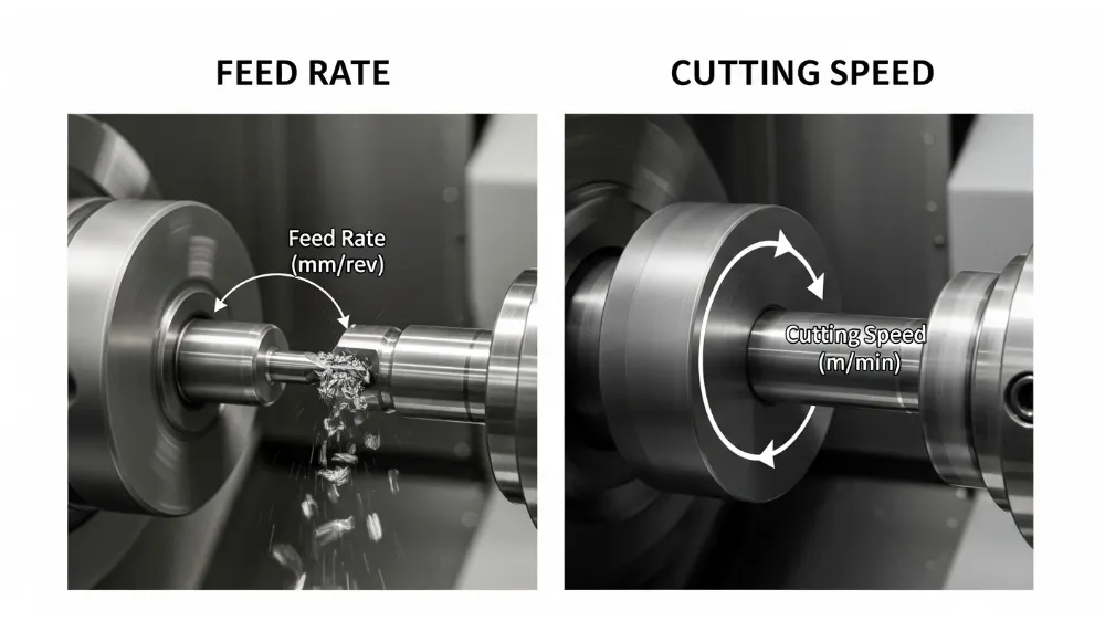
Feed rate refers to the speed at which the cutting tool—or the workpiece—advances relative to the material being cut. It is typically expressed as distance per revolution (mm/rev or in/rev) for turning operations, and distance per minute (mm/min or in/min) for milling or drilling.
Feed rate directly affects how much material is removed in a single pass and has a significant influence on:
- Chip load: The thickness of the material removed by each tooth or cutting edge.
- Surface finish: Higher feed rates often produce rougher finishes.
- Tool engagement: Faster feeds increase cutting forces and can accelerate wear.
In simple terms, feed rate controls the rate of material engagement. If you imagine a saw cutting through wood, the feed rate describes how fast the saw blade is pushed into the material.
Why Feed Rate Matters
Getting feed rate right is critical for:
- Balanced cutting forces: Too low a feed can lead to rubbing and work hardening, while too high can cause tool breakage.
- Predictable cycle times: Accurate feed rates reduce scrap and rework in production environments.
- Consistent surface quality: Proper feeds contribute to smoother finishes in final parts.
Understanding Cutting Speed
Cutting speed describes how fast the material is cut at the tool‑workpiece interface, usually measured as surface speed (m/min or ft/min). It represents the linear speed at which the cutting edge passes along the surface of the workpiece.
In turning, cutting speed is computed based on spindle RPM and workpiece diameter. In milling, it depends on spindle speed and cutter radius.
Why Cutting Speed Is Critical
Cutting speed is directly tied to:
- Tool life: Higher cutting speeds generate more heat, accelerating wear.
- Thermal stress: Excessive speeds can cause thermal deformation in both workpiece and tool.
- Material compatibility: Harder materials generally require lower cutting speeds.
Think of cutting speed as how fast the “edge” is moving through the material, impacting heat generation and fracture mechanisms in the tool.
Feed Rate vs Cutting Speed — Key Differences
While both feed rate and cutting speed are machining parameters, they differ in definition, purpose, and impact:
- Definition
- Feed Rate: The distance the tool advances relative to the workpiece per unit time.
- Cutting Speed: The velocity at which the cutting edge moves across the surface of the workpiece.
- Units
- Feed Rate: mm/min, in/min, mm/rev, in/rev.
- Cutting Speed: m/min or ft/min.
- Primary Impact
- Feed Rate: Influences surface finish, chip size, and mechanical load.
- Cutting Speed: Affects heat generation, tool wear, and cutting efficiency.
- Control Variables
- Feed Rate: Adjusted by varying feed into the part or per revolution.
- Cutting Speed: Adjusted by changing spindle speed or material removal strategy.
- Tool Life Relationship
- Feed rate increases mechanical load on each cutting edge.
- Cutting speed predominantly affects thermal generation and wear mechanisms.
Understanding both allows machinists to tune cutting parameters for specific materials, tool geometries, and machine capabilities.
How to Calculate Feed Rate and Cutting Speed
Cutting Speed (Vc)
Cutting speed is calculated as:
Vc = π × D × RPM / 1000
Where:
Vc = cutting speed (m/min)
D = workpiece/tool diameter (mm)
RPM = spindle speed
Manufacturers provide recommended cutting speeds based on material type and tooling.
Feed Rate (F)
Feed rate in milling is often calculated as:
F = fz × Z × RPM
Where:
F = feed rate (mm/min)
fz = feed per tooth (mm/tooth)
Z = number of teeth on the cutter
RPM = spindle speed
For turning operations, feed per revolution (mm/rev) is used.
Impact on Tool Life and Surface Finish
Choosing the right feed rate and cutting speed has a dramatic effect on:
Tool Life
High cutting speeds increase heat buildup at the cutting edge, weakening tool coatings or substrates and reducing tool life. Conversely, low cutting speeds reduce thermal stress but may increase mechanical wear.
Feed rate influences how much chip load each cutting edge carries. Too high a feed causes shock loading and premature wear or breakage; too low can result in chattering and rubbing.
Surface Quality
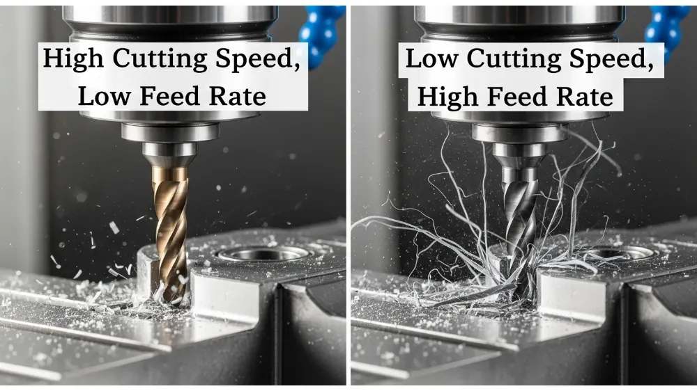
Fine surface finishes typically require moderate cutting speeds combined with lower feed per tooth. Roughing operations that remove large volumes of material often use higher feeds at controlled cutting speeds to balance efficiency and finish.
Optimizing Feed Rate and Cutting Speed Together
Machining optimization is about balance. The highest material removal rates occur when feed rate and cutting speed are tuned together:
- Increase feed rate gradually for roughing passes while controlling cutting speed to avoid excessive heat.
- For finishing, reduce feed per tooth and adjust cutting speed for thermal stability and surface integrity.
- Use manufacturer recommendations and tooling charts as starting points.
- Consider tool geometry, coating, and coolant application when tuning both parameters.
Modern CNC machines often include adaptive control features that monitor cutting conditions and automatically adjust feed or speed for optimal performance.
Common Mistakes When Setting Machining Parameters
Many shops still set feed rates and cutting speeds based on feel or experience alone. This can lead to:
- Too aggressive feed rates, causing tool fracture and poor finishes.
- Excessive cutting speeds, resulting in thermal damage and shortened tooling life.
- Incorrect feeds for tool type, such as using end mill feeds for drill operations.
Understanding the difference between feed rate vs cutting speed empowers operators to define parameters based on physics and material science, not just guesswork.
Material Considerations
Different workpiece materials demand unique combinations of feed and speed:
- Aluminum: Can run higher cutting speeds owing to good thermal conductivity, but requires careful chip evacuation.
- Stainless Steel: Typically needs lower cutting speeds to prevent work hardening and tool heat buildup.
- Titanium and Inconel: Require lower cutting speeds and moderate feeds due to poor thermal conductivity and high chemical affinity with tooling.
- Plastics and composites: Need controlled feeds to avoid melting or delamination.
Selecting correct parameters for the material enhances process stability and part quality.
Role of Machine and Tooling
Not all machines can maintain high speeds or feeds due to rigidity and horsepower limits. Similarly, cutting tools vary by:
- Geometry: Edge angles and chip breakers influence optimal feeds.
- Coating: Coatings like TiAlN or diamond provide thermal barriers allowing higher cutting speeds.
- Material: Carbide, HSS, ceramic — each tooling medium has specific feed and speed envelopes.
Take advantage of tooling manufacturer guides and machine load feedback to dial in the right settings.
Advanced Machining Strategies
Adaptive machining techniques like high‑efficiency milling (HEM) and high‑speed machining (HSM) rely on precise control of both feed rate and cutting speed. These methods keep chip load consistent while controlling heat buildup, often requiring CAM programming adjustments.
Using simulation tools to preview tool paths and cutting loads helps avoid collisions, excessive tool engagement, and unstable cutting conditions.
Real‑World Example: Milling a Steel Block
Imagine milling a hardened steel block with a 20 mm end mill:
- Recommended cutting speed for the tooling in steel might be 180 m/min.
- Given the cutter diameter and machine limits, calculate RPM.
- Select an initial feed per tooth based on tool manufacturer’s specs.
- Adjust based on actual cutting results, surface finish, and tool wear patterns.
This process illustrates how feed rate vs cutting speed decisions directly affect machining outcomes.
Measuring and Monitoring During Machining
Modern machine tools incorporate sensors that track spindle load, vibrations, and tool wear. Feedback can trigger feed reduction or spindle speed changes to prolong tool life or maintain part accuracy.
Tool condition monitoring (TCM) systems help automate adjustments, reducing reliance on fixed feed and speed settings.
Frequently Asked Questions (FAQ)
Q1: What is the main difference between feed rate and cutting speed?
Feed rate controls how fast the tool advances into the material, while cutting speed describes how fast the tool edge moves along the surface of the workpiece.
Q2: How do feed rate and cutting speed affect tool life?
High cutting speeds increase heat, accelerating wear; inappropriate feed rates can overload the cutting edge mechanically.
Q3: Are feed rate and cutting speed interchangeable?
No. They represent different physical phenomena and must be set independently based on tooling, material, and machine capabilities.
Q4: Which parameter is more critical for surface finish?
Both matter, but feed per tooth often has a more direct effect on surface roughness than cutting speed alone.
Q5: How are these parameters adjusted in CNC programming?
Feeds and speeds are defined in the toolpath settings. CAM software allows specification of both based on material and cutter data.
Q6: Can coolant change optimal feeds and speeds?
Yes. Coolants reduce temperature, enabling higher cutting speeds and potentially higher feed rates, depending on material and tool.
Conclusion
Mastering the interaction between feed rate vs cutting speed is essential for efficient machining and high‑quality manufacturing. While feed rate dictates chip load and material engagement, cutting speed governs thermal conditions and tool life. Balancing both — through calculation, experimentation, and real‑time monitoring — ensures optimized production processes, reduced tooling costs, and superior part quality.
By understanding these fundamentals and adapting them to specific materials and machine capabilities, manufacturers can significantly enhance performance and reduce waste in CNC and conventional machining operations.