


Die-Casting Mold Design Guide: Key Factors Affecting Part Quality and Cost
The design of a mold for industrial die casting is critical to the process because it influences accuracy, surface quality, timing, and cost. A die must achieve balance and control for the flow of metal, removal of air, the transfer and cooling of the metal, solidification, and ejection. It must do this while enduring physical and thermal stress.
Each project has different requirements in terms of shape, material, tolerance, volume, and the need for post-processing. Thus, each project calls for a different custom mold. Best practices in the industry consider tooling as part of a system with alloy selection, tolerance, the process of production, and Quality Control.
How the Industrial Die Casting Cycle Works
A die consists of an assembled and a component part, both of which are constructed from hard steel. Once the die is filled with molten metal, the metal is subjected to trimming and other subsequent operations.
•Die Closing: Both the assembled and component parts of the die close and are locked into place.
•Metal Injection: The runners and gates are charged with liquid metal.
•Solidification: The injected metal cools and solidifies as the die warms up.
•Part Ejection: A mechanism either pushing or pulling, removes the solidified part from the die.
•Post-Processing: The additional metal and surplus material is removed.
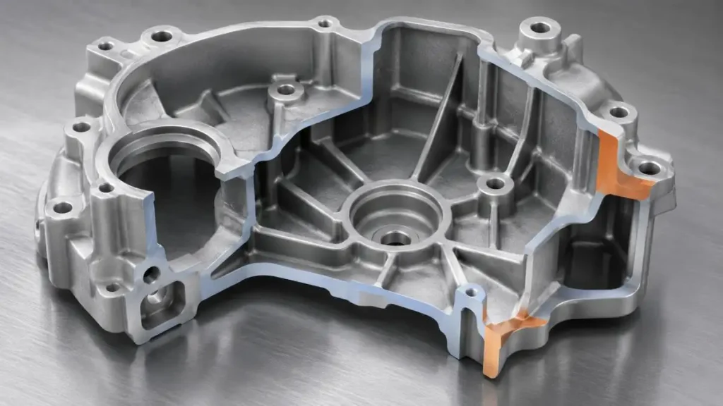
1. Component Geometry and Wall Thickness
The design of the component affects the completeness of the filling of the mold and the uniformity of the cooling. Different thicknesses of sections can lead to distortion and can also trap air.
•Wall Thickness: Walls should be of uniform thickness. Avoid abrupt finish.
•Fillets: Flow and distortion are minimized by the reduction of the abrupt finish.
•Draft: Surfaces should have a slight draft in the direction of die opening.
•Ribs and Bosses: adding material should be avoided. A good design incorporates stiffness and mounting features.
•Avoid Undercuts: Slides and cores to accommodate undercuts increase complexity, and cost.
2. Moving Features and the Parting Line
The location and appearance of blemishes, and the dimensional relationships and ejection of the castings are affected by the parting line. The parting line is used to retain the casting on the ejector side and is used to avoid splitting critical surfaces.
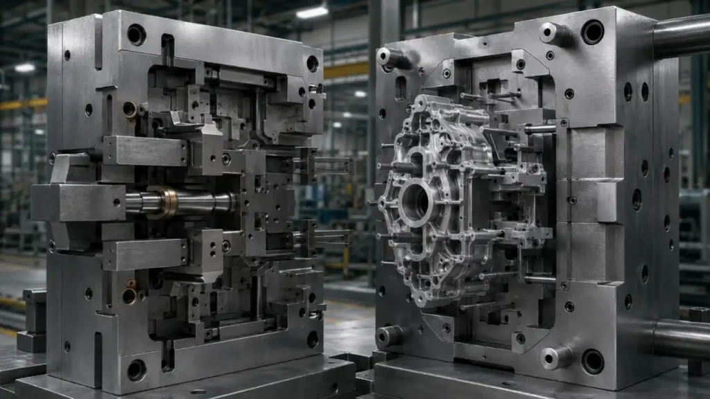
Side cores, slides and inserts can be used to form cross holes or undercuts, but they create additional interfaces, wear points, fitting work and additional steps in the cycle.
3. Design of Runners, Gates, Overflows and Vents
The feeding system must fill the cavity while minimizing the loss of pressure, turbulence, solidification, and trapping of air.
| Element | Function | Effect on Quality and Cost |
| Runner | Delivers molten metal to the cavity | Impacts loss of pressure and balance during filling, and affects return metal |
| Gate | Regulates the flow of metal into the cavity | Impacts the flow pattern, gate marks, and trimming |
| Overflow | Accepts the cooler or oxidized metal | Can enhance the quality of the fill-end, but introduces return metal |
| Vent | Absorbs the air displaced from the cavity | Poor placement may cause porosity or incomplete filling |
| Vacuum System | Helps to eliminate the air from the cavity during filling | Applicable to certain structural, seal, or machined components |
The position of vents, gates, runners and other features should consider the geometry of the component, behavior of the alloy, order of filling, and thermal balance of the die, as well as the surfaces of the component that are critical.
4. Venting and Managing Porosity
Porosity may be due to gas being trapped, shrinkage, lubricant behavior, quality of metal, and variability of the process. Control is typically achieved by several methods:
•Venting: Place vents and overflows in the expected end-of-fill areas.
•Balanced Flow: Design features to avoid flow paths that trap or isolate air.
•Thermal Control: Eliminate uneven cooling and localized hot spots that lead to shrinkage porosity.
•Stable Parameters: Control the shot profile and the temperatures, pressures, and lubrication.
•Vacuum Control: Vacuum-assisted die casting may be applied when part requirements call for tighter leak-tightness, higher structural integrity, or subsequent machining.
5. Cooling and Thermal Balance
The goal of cooling channels is not to simply lower the temperature of the die. There are several issues associated with uneven thermal balance including increased warpage, risk of shrinkage, soldering, variation in cycle time, and heat checking.
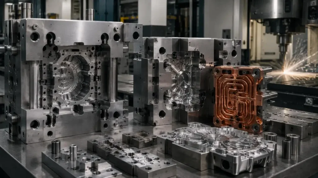
•Hot-Spot Control: Cooling should be placed near thick sections and heat intensive cores.
•Cycle Stability: During production a consistent thermal range should be maintained.
•Dimensional Control: Encourage more uniform solidification and contraction.
•Serviceability: Maintain unobstructed cooling circuits and inserts for future serviceability.
High-conductivity copper alloys can be used in other places around difficult hot spots. Be-Cu alloys pose more problems as Be contaminated particles, dust and mist can be a risk for occupational exposure.
6. Selecting Die Materials
Material selection depends on the casting alloy, operating temperature, die size, component geometry, expected production cycles, heat treatment, and repair strategy.
| Material Group | Relevant Characteristics | Typical Use |
| H13 / 1.2344 / 4Cr5MoSiV1 | Hot strength, toughness, and resistance to heat checking and erosion | Cavities, cores, and inserts |
| 8407 / Orvar 2 Microdized | Premium H13-type grade with controlled processing | Aluminum die-casting tools and demanding hot-work components |
| High-Conductivity Copper Alloy | Rapid local heat transfer but lower hot strength than tool steel | Selected thermal-control inserts |
H13 is commonly used for hot-work and die-casting applications because of its heat-check resistance, toughness, hot hardness, and resistance to erosive action.
8407, Orvar 2 Microdized, 4Cr5MoSiV1, 1.2344, and H13 should not automatically be treated as unrelated materials. They are corresponding standard designations or commercial variants within the H13 family, although cleanliness, processing route, and supplier specifications may differ.
7. Balancing Mold Investment and Part Cost
The lowest mold price does not necessarily produce the lowest cost per saleable part.
| Cost Driver | Potential Benefit | Trade-Off |
| More Cavities | Higher output per cycle | Larger tool and more difficult filling balance |
| Slides and Inserts | Greater design freedom | Added cost, wear, and maintenance |
| Vacuum and Thermal Features | Better process control | Greater tooling complexity |
| Replaceable Wear Areas | Easier repair and servicing | More initial design and fitting work |
| Shorter Stable Cycle | Lower machine time per part | Requires balanced filling, cooling, and ejection |
Evaluation should include production volume, scrap, downtime, maintenance, machining, inspection, and future tool modifications.
SunOn's Industrial Die Casting Support
SunOn supports aluminum and zinc Industrial Die Casting from design review through mold manufacturing and volume production. Its published workflow includes DFM, mold-flow analysis, feed-system design, CNC machining, EDM, mold assembly, trials, tuning, casting, finishing, assembly, and packaging.
The company reports more than 29 years of engineering and manufacturing experience, together with ISO 9001, IATF 16949, and ISO 14001 certifications.
•Engineering Review: SunOn reviews drawings, specifications, alloy selection, volume, tolerances, machining requirements, and cosmetic aspects.
•Filling, venting, and thermal analysis are simulated to identify and eliminate potential defect areas before mold build.
•Mold Manufacturing:Molds are built using CNC machining and EDM (electrical discharge machining), with precision fitting, assembly, and inspection at each stage.
•Trial and Improvement/Modification: Production samples are measured and evaluated during trial runs, with adjustments made before final mold approval.
•Integrated Production: SunOn supports the full production cycle, including die casting, post-processing, assembly, and packaging.
Final Thoughts
A well designed Die Casting mold takes into consideration the flow path of the metal, the geometric design, the filling and venting of the mold, the cooling, and ultimately the cost and durability. Send us your drawings, tolerances, alloy,volume specifications, and finishing details to receive a quotation, even Design For Manufacture (DFM) review, Mold Flow Analysis (MFA), technical consultation, etc..
Q1. Which Materials Are Commonly Die-Cast?
Aluminium and zinc alloys are the most common materials used for Industrial Die Casting.
Q2. What are the Causes of Porosity in Die-Cast Components?
Some of the causes of porosity include trapping gas, shrinkage, inadequate venting, and inconsistent process conditions.
Q3. What is the Effect of Wall Thickness on the Quality of the Cast?
High wall thickness may lead to loss of dimensional accuracy, uneven cooling, and increase in the risk of distortion.
Q4. What are the Effects of Draft Angle Design on Cast Quality?
Draft angles facilitate the removal of cast from the mold, and prevent damage and binding of cast to the mold.
Q5. What is the Role of Vents and Overflows?
They allow the escape of trapped air, and collect the unnecessary metal which solidified during casting and is in the way.
