


Mold Design Guidelines for Lighting Plastic Injection Molding
Lighting Plastic Injection Molding is used for LED lenses, diffusers, reflectors, housings, bezels, brackets and protective covers. Because these parts may need to manage light, heat, appearance and assembly together, mold design directly affects optical quality, dimensional stability and production consistency.
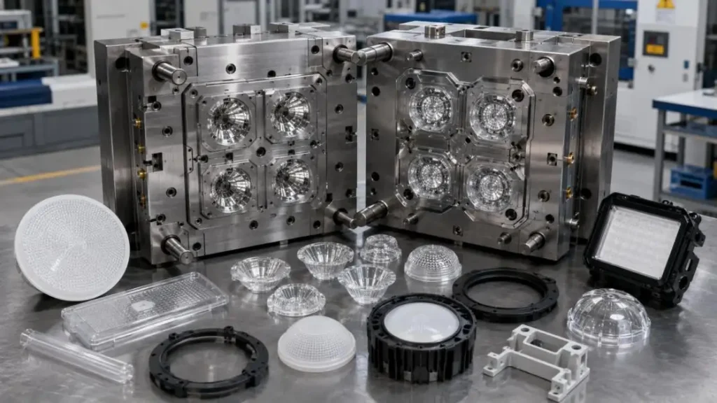
At SunOn, we review geometry, resin, tooling, processing and finishing before mold manufacture begins.
Define the Part's Function
•Transparent Parts: Lenses and clear covers require controlled flow, clean handling and polished cavity surfaces.
•Diffusing Parts: Diffusers may utilize a combination of optical additives, textured tooling, and control of wall thickness.
•Structural Parts: Housings and brackets require stiffness and heat resistance and must have stable mounting features.
•Cosmetic Parts: Visible covers require planned gate, parting-line and ejector locations.
Match the Mold to the Resin
Material choice affects shrinkage, flow, cooling, polishing, venting and tool wear. Common materials for Lighting Plastic Injection Molding include PC and PMMA for optical parts, plus ABS, PC/ABS, PP and nylon for housings and internal components.
| Material | Typical Use | Mold-Design Focus |
| PC | Lenses and diffusers | Drying, stress and surface quality |
| PMMA | Clear covers | Polishing and careful ejection |
| ABS | Indoor housings | Cosmetic finish, ribs and bosses |
| PC/ABS | Structural housings | Heat and dimensional control |
| PP/Nylon | Clips and internal parts | Shrinkage, moisture and wear |
Covestro specifies that Makrolon polycarbonate should be dried before molding and contain no more than 0.02% residual moisture; its guidance lists 120°C drying. Actual settings should follow the selected grade's data sheet.
Keep Wall Thickness Consistent
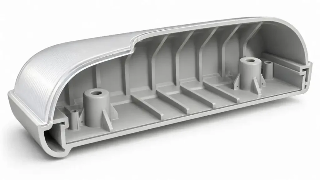
Uniform walls support balanced filling, packing and cooling. Sudden changes in wall thickness lead to voids, shrinkage, and sink marks.
•Mix Incrementally: When layering, keep all layers of equal thickness.
•Coring: There may be some material removal from corners, bosses and protrusions.
•Stiffness: Use ribs to increase stiffness.
•Corners: Smooth and rounded corners enhance flow and reduce stress concentration.
BASF further advises uniform thicknesses for walls to avoid disruptive effects on pressure balances and on the quality of the part.
Consideration of Draft, Ejection and Surface Quality
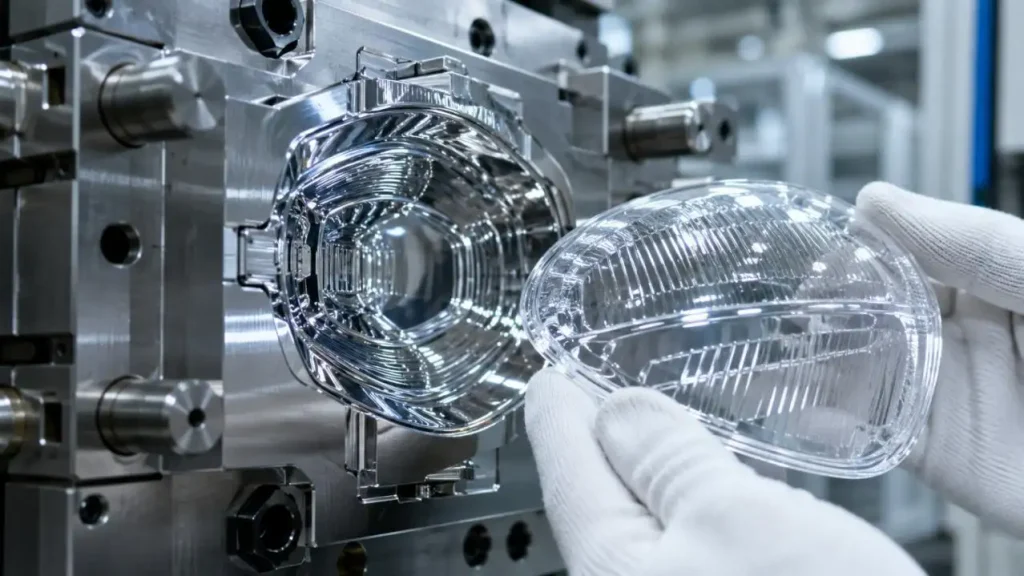
Draft eases part release and protects polished, textured, or cosmetic surfaces from damage during ejection.
•Polished Surfaces: Draft should be provided to minimize drag marks and to avoid the appearance of optical distortions.
•Textured Surfaces: Draft should be increased with texture depth and friction.
•Ejector Placement: Ejectors should be placed in supported areas, concealed from cosmetic surfaces.
•Large Diffusers: Large ejector pins or diffuser plates are used to distribute ejection force and reduce whitening or deformation on visible surfaces.
Tool steel, EDM texture and polishing should match the required gloss, diffusion and appearance. Parting lines should remain away from primary illuminated surfaces where practical.
Optimise Gates, Runners, Venting and Cooling
In Lighting Plastic Injection Molding, the feed and thermal systems affect flow marks, weld lines, packing, air traps and warpage.
| Design Decision | Engineering Objective |
| Gate location | Keep gate marks away from illuminated areas |
| Gate type | Match resin, wall thickness and trimming needs |
| Runner balance | Reduce cavity-to-cavity variation |
| Venting | Release trapped air at end-of-fill regions |
| Cooling | Maintain a reasonably uniform cavity temperature |
Fan, edge, pinpoint and hot-runner gates may all be suitable. Covestro notes that the gate system should allow holding pressure to act on the part for a sufficient period.
Simulation can support gate placement, runner sizing, cooling and warpage evaluation before steel is cut. Autodesk identifies these as core Moldflow applications.
Select Tooling for the Production Plan
Single-cavity, multi-cavity, rapid and production tooling serve different volume and cost targets. SunOn's capabilities in custom molds, rapid tooling, multi-cavity production, insert molding, overmolding and 2K molding.
Our typical quantities from 1,000 to more than one million parts, lead times of 7–30 days and general tolerances around ±0.1 mm. These figures are project-dependent because resin, geometry, inspection method and tool complexity affect the final plan.
Validate Before Mass Production
A controlled Lighting Plastic Injection Molding launch normally includes DFM review, trial samples, measurement and assembly checks.
•Dimensional Inspection: Validate the fit of parts and the existence and proper arrangement of sealing and mounting features.
•Visual Inspection: Assess the marks left by the flow and check for weld lines, sinks, flashes, scratches and examine the surface gloss.
•Optical Inspection: Review transmission, haze, diffusion and visible stress where required.
•Functional Testing: Confirm clips, threads, inserts, seals and mating components.
SunOn's Manufacturing Perspective
SunOn was established in 1997 and operates a 32,000-square-metre facility with more than 1,000 personnel, holding ISO 9001, ISO 14001, and IATF 16949 certifications.
This integrated scope is particularly relevant for Lighting Plastic Injection Molding, where mold decisions need to connect with coating, printing, metal-part integration, and final assembly. Our role is to review manufacturing risks early and align the tool with the required appearance, function, and production volume.
Closing Words
Reliable Lighting Plastic Injection Molding begins with a mold designed around optical, structural, thermal and cosmetic requirements. Material behaviour, wall thickness, draft, gating, venting, cooling, ejection and surface finish should operate as one system. Early DFM review and trial validation provide a practical path from concept to repeatable production.
FAQs
Q1. Is plastic injection molding suitable for optical lighting components?
Yes. With the right materials and precision-polished tooling, it can produce optical lenses, light diffusers, and optically clear covers.
Q2. Which materials are typically used?
Choice of material depends on the design requirements, optical versus structural, and may include: PC, PMMA, ABS, PC/ABS, PP, and nylon.
Q3. What is the significance of maintaining uniform wall thickness?
Uniform wall thickness promotes even cooling and consistent shrinkage, reducing cosmetic defects such as sink marks and warpage.
Q4. What are the impacts of gate placement on lighting components?
Placement of gates will influence flow marks, weld lines, surface quality and appearance, and overall material distribution.
Q5. What are the main causes of defects in transparent lighting components?
Defective transparency in lighting components is usually due to poor drying of the resin, insufficient or excessive cooling, and poor control of processing temperatures.
