


PEEK CNC Machining: Grades, DFM, Annealing, and RFQ Guide
PEEK CNC machining is used when a custom plastic component requires a combination of thermal performance, chemical resistance, mechanical strength, wear resistance, electrical insulation, and relatively low weight.
However, selecting “PEEK” is not enough to define a manufacturable part. Unfilled, glass-filled, carbon-filled, bearing, conductive, and regulated grades can behave differently during machining and in service.
Part geometry, stock condition, residual stress, heat generation, clamping, tolerances, cleanliness, and inspection requirements also influence the machining route.
For mechanical engineers and technical buyers, the main question is therefore not simply whether PEEK can be machined. It is whether the selected grade and design can be machined, stabilized, inspected, and repeated without unnecessary distortion, tool wear, material waste, or acceptance risk.
PEEK CNC Machining at a Glance
| Project Requirement | Typical Direction |
|---|---|
| General precision plastic parts | Start by reviewing unfilled PEEK |
| Higher stiffness and dimensional stability | Compare glass-filled and carbon-filled grades |
| Bearings, guides, and sliding components | Review a dedicated bearing or wear grade |
| Electrical or semiconductor application | Confirm conductivity, ESD, purity, and outgassing needs |
| Medical or food-related project | Specify the exact compliant commercial grade |
| Round bushings, rings, and sleeves | CNC turning may be suitable |
| Housings, plates, and multi-face parts | CNC milling or multi-axis machining |
| Tight-tolerance or thin-wall geometry | Review stock stress, machining sequence, and annealing |
| Stable high-volume production | Compare CNC machining with injection molding |
What Is PEEK CNC Machining?
PEEK CNC machining produces custom parts from rods, plates, tubes, rings, or other semi-finished stock by removing material with computer-controlled equipment.
Common operations include:
- CNC milling
- CNC turning
- Drilling and reaming
- Thread milling and tapping
- Slotting and pocketing
- Multi-face machining
- Grinding and lapping
- Deburring and edge finishing
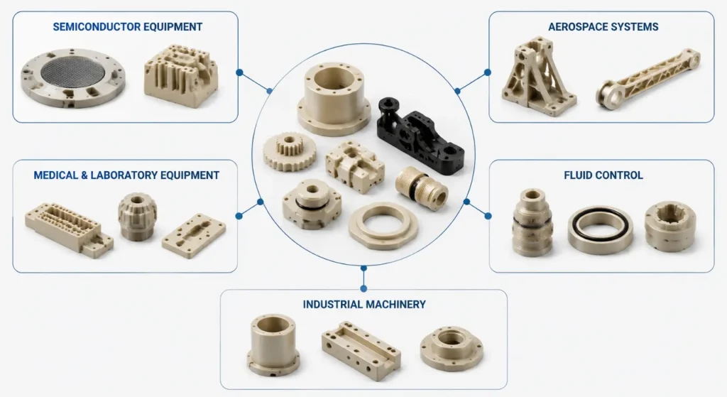
Typical machined PEEK components include:
- Bushings, bearings, and wear rings
- Electrical insulators and connectors
- Valve seats and fluid-system components
- Seals, spacers, and washers
- Semiconductor equipment fixtures
- Pump and compressor components
- Laboratory instrument parts
- Lightweight brackets and housings
- Prototype parts for functional validation
PEEK is generally machinable using equipment and methods similar to those used for metals and other engineering plastics, but machining parameters, tooling, cooling, workholding, and material preparation must be adapted to the polymer.
Projects involving several plastic machining processes can also be reviewed through SunOn’s CNC plastic machining services.
Choosing the Correct PEEK Grade
The RFQ should identify the exact commercial grade rather than stating only “PEEK.” The base resin, filler type, filler percentage, color, stock form, certification, and regulatory status can all affect the finished component.
Unfilled PEEK
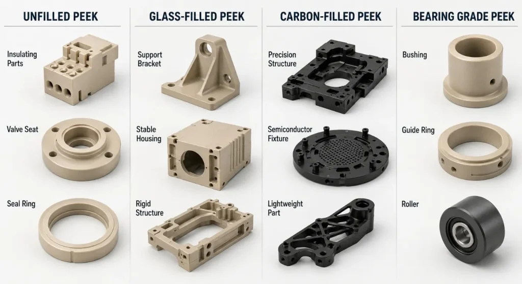
Unfilled PEEK is often considered for general precision parts requiring a balance of:
- Mechanical performance
- Chemical resistance
- Electrical insulation
- Wear performance
- Dimensional stability
- Lower density than metal
It is commonly used for insulators, valve parts, seals, spacers, laboratory components, and general industrial parts.
Unfilled material is not automatically the best option for every project. Static loading, creep, thermal expansion, friction, and required stiffness should still be evaluated.
Glass-Filled PEEK
Glass-filled PEEK is used when increased rigidity, creep resistance, and dimensional stability are required.
Possible applications include:
- Structural supports
- Insulating components
- High-temperature fixtures
- Static-load parts
- Dimensionally sensitive housings
Glass fibers increase tool abrasiveness and may influence surface finish, edge quality, and the behavior of thin sections.
Carbon-Filled PEEK
Carbon-filled PEEK may provide greater stiffness, improved thermal dimensional stability, and different electrical or thermal behavior compared with unfilled material.
It can be considered for:
- High-stiffness components
- Precision structural parts
- Wear components
- Semiconductor equipment
- Mechanically loaded fixtures
The exact compound must be confirmed because carbon-filled grades do not all have the same fiber content, conductivity, wear behavior, or regulatory documentation.
Bearing and Functional Grades
Modified PEEK grades may contain PTFE, graphite, carbon fiber, or other additives to support friction, wear, conductivity, ESD control, detectability, or application-specific requirements.
Ensinger’s PEEK material portfolio includes unfilled, glass-filled, carbon-filled, bearing, conductive, antistatic, semiconductor, medical, and detectable grades.
A generic grade should not be substituted for a specified functional or regulated material without customer approval.
Why PEEK Machining Requires Special Control
PEEK is often described as dimensionally stable and machinable, but precision results still require control of several polymer-specific risks.
Residual Stress and Annealing
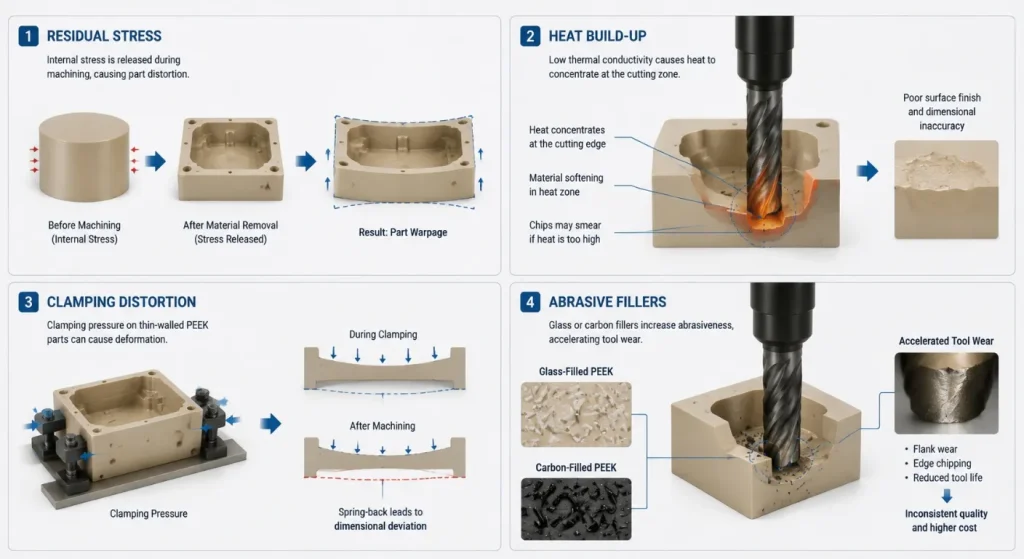
Residual stress may come from extrusion, compression molding, stock-shape production, or previous machining operations.
When material is removed, these stresses can be released and cause:
- Warping
- Bowing
- Diameter changes
- Flatness loss
- Movement after unclamping
- Dimensional changes between roughing and finishing
According to the Victrex finishing and machining guide, annealing may be required before machining or as an intermediate step. A second annealing stage may be considered when a large amount of material is removed before final machining.
Annealing is not a universal fixed cycle. The material supplier’s instructions, stock thickness, grade, geometry, and required tolerance should determine the process.
Heat Build-Up
PEEK and other polymers conduct cutting heat less effectively than metals. Excessive local heat may affect dimensions, surface finish, chip behavior, and internal stress.
Heat control may involve:
- Sharp cutting edges
- Stable feeds
- Controlled cutting depth
- Suitable coolant or air
- Chip evacuation
- Reduced rubbing
- Sufficient cooling between operations
Coolant selection must also consider cleanliness, compatibility, and the final application.
Clamping Distortion
PEEK has a lower modulus than most metals. Excessive fixture pressure can deform the workpiece during machining.
The part may measure correctly while clamped but move after release. Workholding should support the component without crushing thin walls or distorting bores and sealing surfaces.
Abrasive Reinforced Grades
Glass- and carbon-filled PEEK can wear cutting tools faster than unfilled material.
Victrex recommends carbide, coated-carbide, or diamond-tipped tooling for appropriate applications because unsuitable tools can produce rapid wear and poor surface quality.
Match the CNC Process to the Geometry
CNC Milling
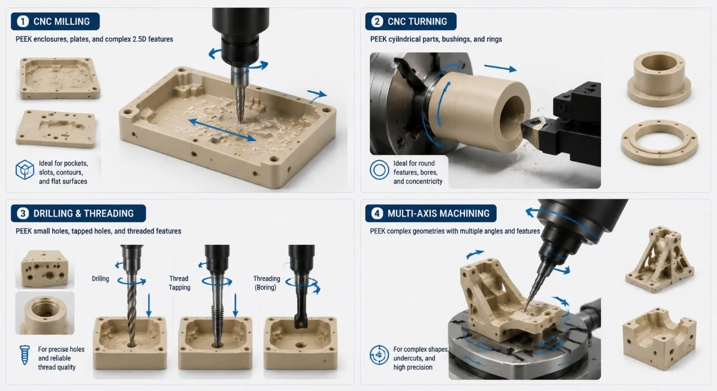
CNC milling is commonly used for:
- Plates and brackets
- Housings
- Pockets and slots
- Insulators
- Manifold-style components
- Sealing faces
- Semiconductor fixtures
- Multi-hole patterns
Three-axis machining may be sufficient for accessible prismatic geometry.
CNC Turning
CNC turning is suitable for round parts such as:
- Bushings
- Sleeves
- Rings
- Washers
- Valve seats
- Spacers
- Rollers
- Cylindrical seals
Turning can help maintain concentric relationships between bores, outside diameters, grooves, shoulders, and sealing features.
Mixed geometry may require the CNC turning and milling process or several controlled setups.
Multi-Axis Machining
Multi-axis machining may improve access to angled holes, compound surfaces, multi-face features, and complex fixtures.
Reducing repositioning may support better feature relationships, but multi-axis equipment cannot compensate for incomplete datums, excessive tolerances, or unstable thin-wall geometry.
Key DFM Risks in Machined PEEK Parts
Thin Walls
Thin walls can flex under cutting and clamping forces. They may also move as residual stress is released.
Possible improvements include:
- Increasing wall thickness
- Adding temporary support material
- Using balanced material removal
- Separating roughing and finishing
- Inspecting after stress relief
Deep Pockets
Deep pockets require longer tools and remove a large amount of material from one region.
This may increase vibration, heat, machining time, distortion, and material waste. Reducing depth or increasing internal radii can improve access and stability.
Small and Deep Holes
Small-diameter or deep holes can create chip evacuation and heat-control problems.
The drawing should clearly define:
- Hole diameter
- Drilled depth
- Effective depth
- Positional tolerance
- Surface requirement
- Whether the hole is through or blind
Deep Threads
PEEK threads can be machined, but deep blind threads and thin material around threaded features can increase deformation and chip-control risks.
Specify the minimum effective thread engagement rather than unnecessarily extending full thread depth.
Excessive Tolerance Coverage
Not every PEEK dimension needs a tight tolerance.
Critical requirements should focus on:
- Fits
- Sealing
- Concentricity
- Flatness
- Bearing alignment
- Hole position
- Assembly interfaces
- Functional thickness
General dimensions can use an appropriate title-block tolerance.
Tolerances and Inspection Should Reflect Polymer Behavior
Tolerance capability depends on:
- PEEK grade
- Stock condition
- Part size
- Wall thickness
- Material removal
- Temperature
- Workholding
- Annealing strategy
- Measurement method
- Time between machining and inspection
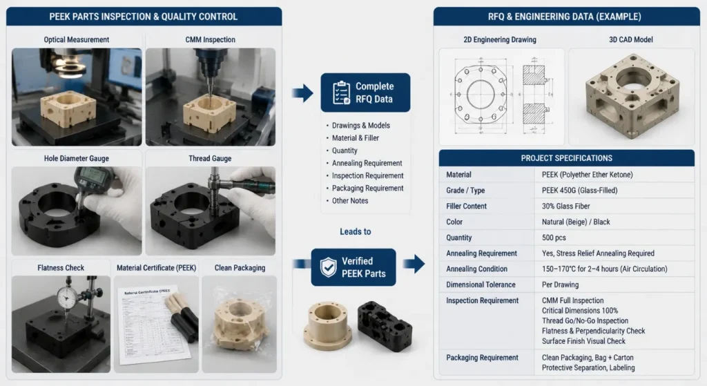
The inspection plan may include:
- Calipers and micrometers
- Bore and pin gauges
- Thread gauges
- Optical measurement
- Coordinate measuring machines
- Flatness inspection
- Surface-roughness measurement
- Visual edge and burr inspection
- Material certificates
- Cleanliness records
Temperature-sensitive precision parts should be allowed to stabilize before final measurement. The drawing should also identify the required inspection temperature or standard where this affects acceptance.
PEEK CNC Machining vs. Injection Molding
CNC machining is commonly selected for:
- Prototypes
- Functional testing
- Low-volume production
- Design revisions
- Complex low-quantity parts
- Projects without mold investment
- Machining features into molded or extruded blanks
SunOn’s low-volume CNC machining support can be used when quantities do not justify dedicated production tooling.
PEEK injection molding may be considered when:
- Geometry has stabilized
- Repeat volume is sufficiently high
- Mold investment is justified
- Material waste reduction is important
- The component is suitable for molding
- The required material and molding equipment are available
Machined and molded PEEK parts should not automatically be treated as mechanically identical. Crystallinity, thermal history, fiber orientation, and production method can influence performance.
For lower-temperature or less chemically demanding applications, a more economical engineering plastic may also be sufficient. SunOn’s Delrin CNC machining guide provides a useful comparison for parts focused on stiffness, sliding performance, and general machinability.
From Material Review to Delivery
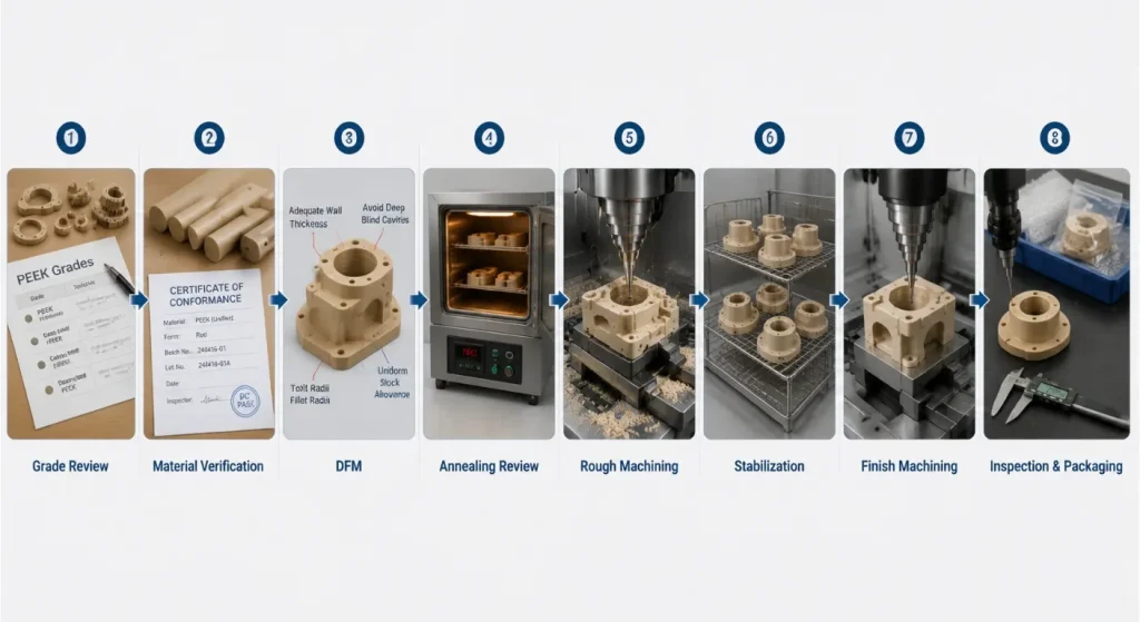
A controlled PEEK CNC machining project commonly follows these stages:
- RFQ review: Confirm the application, exact grade, quantity, drawing, finish, certification, and delivery requirements.
- Material verification: Review the stock form, batch information, certificates, and supplier documentation.
- DFM review: Identify stress, wall-thickness, clamping, tool-access, tolerance, and burr risks.
- Stress-relief planning: Determine whether pre-machining or intermediate annealing is required.
- Rough machining: Remove material in a controlled and balanced sequence.
- Finish machining: Complete functional dimensions after stabilization or intermediate processing.
- Cleaning and inspection: Verify dimensions, surfaces, edges, documentation, and cleanliness requirements.
- Protective packaging: Prevent scratching, contamination, deformation, and part-to-part contact.
What to Include in a PEEK CNC Machining RFQ
Provide:
- Controlled 2D engineering drawing
- 3D CAD model
- Exact PEEK grade and manufacturer, where required
- Filler type and percentage
- Stock form or material condition
- Prototype and production quantities
- Functional datums and GD&T
- Critical dimensions and fits
- Surface-roughness requirements
- Thread, insert, and edge specifications
- Annealing or stress-relief requirements
- Material certificates and traceability
- Cleaning and contamination limits
- Inspection and reporting requirements
- Packaging and labeling requirements
- Delivery destination and target date
SunOn’s CNC machining quotation guide provides additional information on preparing complete project files.
Frequently Asked Questions
1. Which PEEK Grade Is Best for CNC Machining?
Unfilled PEEK is a practical starting point for many precision components. Glass-filled, carbon-filled, bearing, conductive, or regulated grades should be selected only when the application requires their specific stiffness, wear, electrical, or documentation characteristics.
2. Does PEEK Always Need Annealing Before Machining?
Not every PEEK part requires the same annealing process. The need depends on the stock condition, material removal, geometry, wall thickness, tolerance, and material supplier’s recommendations.
3. What Tolerances Can PEEK CNC Machining Achieve?
Tolerance capability depends on grade, part size, residual stress, temperature, workholding, machining sequence, and inspection method. Tight tolerances should be limited to functional features and reviewed from the controlled 2D drawing.
4. Can Glass-Filled and Carbon-Filled PEEK Be CNC Machined?
Yes, both can be machined, but their fibers increase tool abrasiveness and can affect edge quality and surface finish. Carbide, coated-carbide, or diamond tooling may be required depending on the grade and production quantity.
5. Should PEEK Parts Be CNC Machined or Injection Molded?
CNC machining is generally suitable for prototypes, design revisions, complex low-volume parts, and projects without mold investment. Injection molding may become more economical when geometry is stable and repeat volume justifies tooling.
6. What Information Is Needed for a PEEK Machining Quote?
Provide 2D and 3D files, the exact PEEK grade, filler content, quantities, tolerances, finish, annealing requirements, certifications, cleanliness, inspection, packaging, and delivery needs. For medical, food, semiconductor, or other controlled applications, include the applicable documentation requirements before quotation.
Conclusion
Reliable PEEK CNC machining begins with the exact material grade and a design that reflects the behavior of high-performance polymers.
Unfilled PEEK supports many general precision components. Glass-filled and carbon-filled grades may improve stiffness and dimensional performance, but they also change tooling and surface requirements. Bearing, conductive, medical, food-contact, and semiconductor grades must be specified by their exact commercial designation and supporting documentation.
Residual stress, cutting heat, clamping pressure, tool wear, wall thickness, annealing, and inspection conditions should be reviewed together. Advanced equipment alone cannot compensate for an unspecified PEEK grade, unstable geometry, or incomplete acceptance requirements.
To request a manufacturability review, contact SunOn with your 2D drawing, 3D CAD model, exact PEEK grade, quantities, critical tolerances, certification, cleanliness, and inspection requirements.
