


Quality Control and Inspection Methods for Robotics CNC Machining
Robotics CNC Machining produces robot joints, motor mounts, bearing housings, shafts, end-effector plates, sensor enclosures, and structural brackets. Because these parts combine moving interfaces and closely aligned assemblies, inspection must evaluate both dimensional size and geometric relationships.
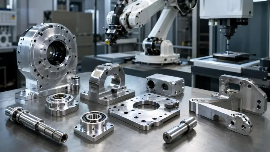
A practical quality plan links each drawing requirement to part function, machining risk, and a suitable measurement method rather than applying the tightest tolerance everywhere.
The Importance of Inspection
Even Small changes in important features may impact alignment, friction, backlash, vibration, and the efficiency of assembly.
•Bearing and Shaft Fits: The rotational characteristics depend on bearing bore and shaft diameters, roundness and runout.
•Motor Interfaces: Features of mounting holes aid in the alignment of motor-to-shaft interfaces.
•Robot Arm Structures: Geometry of assembly is affected by the position of the holes and their flatness.
•End-Effectors: The flatness of the mounting face and the position of the thread affect the repeatability of installation of tools.
Selecting an Inspection Method
No single method of inspection can check all features of a Robotics CNC Machining. Method of inspection depends on the tolerance and type of feature, accessibility, surface finish, and how many are made.
| Method | Typical Application | Main Consideration |
| Calipers | General lengths, widths, depths, and diameters | Fast, but not good for very small tolerances |
| Micrometers | Shafts, pins, thicknesses, and precision dimensions | Higher resolution with limited access |
| Bore Gauges | Precision checks of bores | Requires a setting standard |
| Pin/Thread Gauges | Go/no-go checks for pins and threaded holes | Checks limit, not values |
| Height Gauge | Measurements of height, steps, and feature location | Requires a surface plate |
| CMM | Hole position and profiles, datum, and GD&T | Requires programming and a measuring environment |
| Vision System | Small slots, edges, profiles, and delicate parts | Inspection is definable by focus and edge contrast |
| Roughness Tester | Surface finish inspection, e.g. Ra | A method of dimensional inspection cannot replace this |
Calipers, Micrometers, and Gauges
During the inspection process, calipers are used at the setup, in-process, and final inspection phases.
•External Measurement: Calipers can measure external features for width, thickness, and outside diameters.
•Internal Measurement: Calipers can measure the internal width of jaws for holes, slots, and openings.
•Depth measurement: The advantage of depth rods is that they can measure the depth of recesses as well as shallow holes.
•Limitations: Results can vary due to conditions of the results, jaw alignment, and operator.
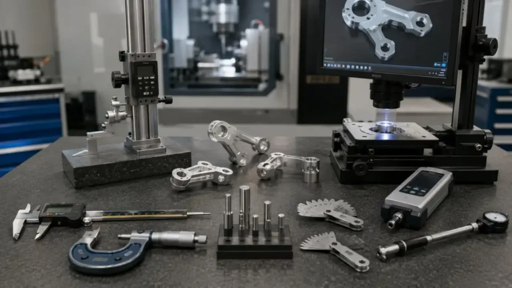
For more precise tolerances on shafts or on the seats of bearings, other instruments such as micrometers or bore gauges should be used.
•Outside Micrometers: Typically employed to measure the outer dimensions of components in precision engineering, such as shafts and pins, as well as measuring walls and precision steps.
•Depth Micrometers: Can measure the depth of various shoulders and the depth of counterbores as well as recesses.
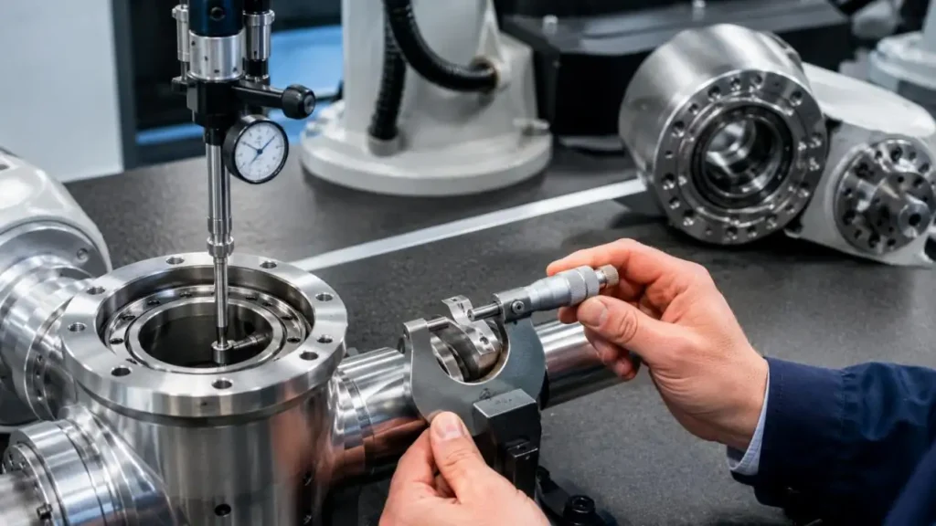
•Bore Gauges: Used to measure the diameter of a bore and to check if the bore is tapered and/or out of round.
•Limit gauges (pin and thread gauges) provide quick go/no-go inspections for repetitive part production.
CMM Inspection for Complex Geometry
A coordinate measuring machine (CMM) defines an inspection volume by creating a 3D Cartesian Coordinate System (CCS) through the measurement of a feature or surface. Measuring machine (CMM) is an essential tool for complex five (5) axis parts featuring a wide variety of geometric tolerances.
Typical CMM checks include the following:
•True Position: The CMM checks mounting and locating holes against the datums.
•Orientation: The CMM checks perpendicular and parallel relations of various surfaces.
•Form: The CMM checks for roundness, flatness, and cylindricity.
•Profile: The CMM checks the deviation of the measured points from the CAD.
•Reporting: Inspection records can be generated digitally by repeatable programs.
Temperature and Surface-Finish Effects
Dimensions change with temperature because materials expand and contract. The recognized reference temperature for industrial dimensional measurement is 20°C, so precision parts and instruments should be thermally stabilized when tight tolerances are involved.
Anodizing, plating, painting, polishing, and powder coating may alter dimensions or surface texture. Critical interfaces may therefore require inspection before finishing, after finishing, or at both stages.
Recommended Quality-Control Workflow
| Stage | Main Activity | Typical Record |
| Design Review | Confirm datums, GD&T, inspection access, and tolerances | DFM and inspection plan |
| Material Control | Verify the specified material grade | Material record |
| Setup Approval | Check fixtures, tools, offsets, and initial features | Setup verification |
| First Article | Inspect dimensions and critical characteristics | First-article report |
| In-Process Control | Monitor tool wear and dimensional drift | Inspection log |
| Final Inspection | Verify dimensions, finish, and appearance | Final report |
SunOn's Robotics CNC Machining Capabilities
SunOn provides CNC machining for aluminum, stainless steel, titanium, brass, PEEK, nylon, and other materials. The capabilities including but not limit to five-axis machining, CMM and caliper inspection, anodizing, painting, plating, polishing, and powder coating.
•Dimensional Accuracy: SunOn's capability ranges from ±0.1 mm to ±0.002 mm.
•Surface Finish: Machined finishes reach down to Ra 0.8 μm.
•Rapid Prototyping: Selected projects are listed with a 72-hour turnaround.
•Low-Volume Production: Published order quantities are between one and one hundred units.
•Tooling Flexibility: Custom parts can be machined without dedicated tooling, keeping low-volume and one-off orders cost-efficient.
The data above indicates available manufacturing capability. The scope of manufacturing solutions is dependent on features such as material, geometry, fixturing, size, finishing, quantity, and inspection.
Main Conclusion
The reliability of robotic motion, fit, and repeatability is dependent on the accuracy of inspection. SunOn uses calipers, micrometers, gauges, vision inspection systems, and CMM to ensure critical dimensions and complex geometric relationships throughout the manufacturing process.
From DFM review and rapid prototyping to the final inspection and delivery, we provide Robotics CNC Machining services for metals and plastics with controlled and traceable services.
Please send us your drawings along with project requirements, for a technical review and quote.
FAQs
Q1. What Is First-Article Inspection?
First-Article Inspection is the process of inspecting the first machined component before starting the production run.
Q2. Why Is Inspection Critical to Robotics Parts?
Inspections assess and ensure the proper fit and alignment, the correct range of motion, and consistency in how parts assemble.
Q3. What Does a CMM Measure?
CMM's measure complex dimensions, positions of holes, profiles, and geometric tolerances.
Q4. Do CNC Parts Need Calipers, or Is That a No-Go?
A caliper may be used to check dimensions in the general sense, but it may not be capable for very tight tolerances.
Q5. When Are Micrometers Incorporated in Parts?
Micrometers are incorporated in parts requiring precise measure of diameters and thickness, as in shafts and bearing surfaces.
