
How to Design Parts for 2K Injection Molding
Designing parts for 2K injection molding requires a focus on three key areas. These are material compatibility, wall thickness transitions, and the bond between the layers. A successful design balances these elements perfectly. With extensive experience in manufacturing complex multi-material components, our team has identified the critical design principles that lead to successful outcomes. Proper design is not just about aesthetics; it is about ensuring the final part is strong, functional, and manufacturable.
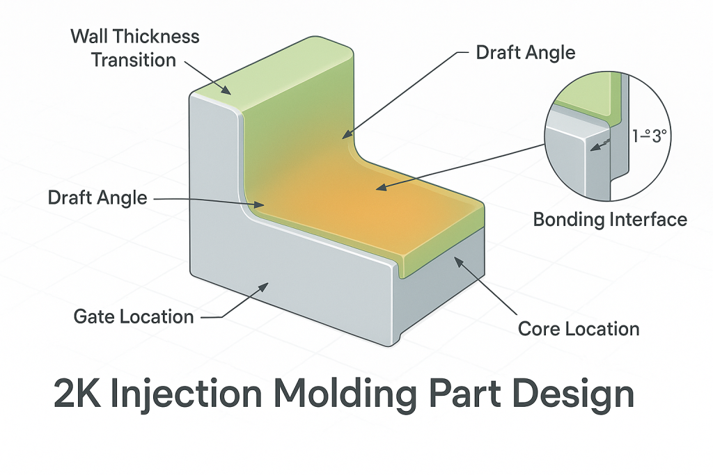
This guide explores the essential rules for 2K part design. We will cover core concepts like wall thickness, draft angles, and gate locations. The article also provides detailed strategies for creating a robust bond between the two materials. Following these guidelines helps prevent common defects like warping, sink marks, and delamination. It ensures the part can be produced efficiently and reliably, meeting the highest quality standards from the very first shot.
The Foundational Principle: Substrate as the Core
In any 2K molded part, the first material shot is called the substrate. This component forms the structural backbone of the entire part. Therefore, its design is the most critical element. The substrate must be rigid enough to withstand the pressure and temperature of the second injection shot without warping or deforming. It provides the foundation upon which the second material, the overmold, is applied.
The geometry of the substrate dictates nearly every other aspect of the design and molding process. It defines the location of the bond line between the two materials. It also influences where gates can be placed and how the part will cool. A well-designed substrate is stable, strong, and optimized for the flow of the second material. Neglecting the design of this core component is a common reason for failure in the overall 2K Injection Molding process. A strong foundation is essential for a successful multi-material part.
How Should You Manage Wall Thickness?
Consistent wall thickness is one of the most fundamental rules in all of injection molding. This principle is even more critical in 2K molding. Drastic variations in thickness can cause a host of problems, from visual defects to complete structural failure. Managing thickness carefully for both the substrate and the overmold is essential for a high-quality part.
Maintaining Uniform Thickness
Both the substrate and the overmold should have walls that are as uniform in thickness as possible. This allows the molten plastic to flow evenly throughout the mold cavity. It also ensures the part cools at a consistent rate. When some areas are much thicker than others, the thick sections cool slower. This differential cooling causes the material to shrink unevenly, leading to internal stress. This stress can cause warping, sink marks on the surface, or even cracks in the part.
Designing Smooth Transitions
In many designs, changes in wall thickness are unavoidable. When this is the case, the transition from a thick to a thin section must be gradual. A sharp, step-like change creates a point of high-stress concentration. This weakens the part and can become a failure point during use. Instead, use smooth, rounded fillets or a gentle taper to transition between different wall thicknesses. This allows stress to be distributed more evenly across the part, preserving its structural integrity.
The Overmold Thickness Rule
As a general guideline, the overmold layer should be thinner than the substrate layer. A common rule of thumb is to design the overmold to be between 40% and 60% of the substrate's thickness. A thick, bulky overmold can create immense pressure on the substrate during injection. It can also generate enough shrinkage force to warp the entire component as it cools. A thinner overmold is more stable and less likely to cause defects. It also helps reduce material costs and cycle times.
What is the Role of Draft Angles in 2K Design?
Draft angles are a crucial element in designing any molded part. A draft angle is a small taper applied to the vertical walls of a part. This taper makes it much easier to eject the part from the mold without damage. In 2K molding, draft angles are required for both the substrate and the final overmolded component. Without proper draft, parts can get stuck in the mold. This can lead to scuff marks, broken features, or damage to the expensive mold itself.
The amount of draft needed depends on several factors. The depth of the part is one consideration; deeper parts require more draft. The type of material used also plays a role. Most importantly, the texture of the surface has a major impact. A smooth, polished surface may only need 0.5 to 1 degree of draft. However, a part with a textured finish, like those used for Soft Touch Grips 2K Molding, requires significantly more draft. A light texture might need 3 degrees, while a heavy, leather-like grain could require 5 degrees or more. The texture creates tiny undercuts that the part must be able to clear during ejection.
Designing for a Strong Bond Between Materials
The interface where the two materials meet is the most important area in a 2K part design. The entire purpose of the process is to create a permanent bond between the substrate and the overmold. This bond can be achieved through chemical adhesion or mechanical interlocks. A good design will maximize the strength of this bond, regardless of the method used.
Leveraging Chemical Adhesion
As discussed in guides on 2k injection molding materials, a chemical bond is formed when two compatible polymers fuse at the molecular level. While this is primarily a function of material science, part design can enhance this chemical bond. The goal is to maximize the surface area at the interface between the two materials. A larger contact area provides more space for the materials to fuse. Designing a wide, consistent contact zone is more effective than a thin, narrow one. The design should also promote good flow of the overmold material across the substrate's surface.
Creating Mechanical Interlocks for Incompatible Pairs
When materials are not chemically compatible, the designer must create a mechanical bond. This involves adding physical features to the substrate that the overmold material can flow into and lock onto. This method is highly effective but requires careful planning from the beginning of the design process.
There are several proven techniques for creating strong mechanical interlocks.
- Grooves or Channels: The simplest method is to design recessed channels or grooves into the substrate. The overmold material fills these channels, creating a solid connection that resists pulling or peeling forces.
- Through-Holes: For an even stronger bond, designers can add holes that go completely through the substrate. The overmold material flows through these holes, forming connections on both sides of the substrate. This acts like a plastic rivet, securely locking the overmold in place.
- Undercuts: An undercut is a feature that creates a ledge or hook. The overmold flows under this ledge and is physically trapped once it solidifies. This is very effective at preventing the edge of the overmold from lifting or peeling away.
- Textured Surfaces: Applying a rough or matte texture to the bonding surface of the substrate can significantly improve adhesion. The texture increases the overall surface area and provides small peaks and valleys for the overmold to grip.
Shut-Offs: Defining the Boundary
A shut-off is the area in the mold where the steel surfaces meet to contain the molten plastic. In 2K molding, the shut-off defines the edge of the overmold. A crisp, well-defined boundary is essential for a clean, professional look. A poorly designed shut-off can lead to "flash," where a thin film of plastic escapes the intended area. To prevent this, the design should include a clear step or groove at the edge of the overmold area. This gives the mold a sharp edge to seal against, ensuring no material leaks out.
Where Should You Place Gates?
A gate is the small opening through which molten plastic is injected into the mold cavity. The location of the gate can have a significant impact on the final part quality. In the 2k injection molding process, both the substrate and the overmold shots require careful gate placement. For the substrate, gates should be placed in a non-visible or non-critical area of the part if possible. They should also be located in the thickest section of the part to ensure the cavity fills completely.
For the overmold, gate placement is even more critical. Gating directly onto the substrate should be avoided, as the high-pressure stream of plastic can erode or damage the substrate's surface. Instead, the gate should be positioned to allow the material to flow smoothly across the substrate. Again, gating into the thickest section of the overmold helps ensure proper packing and reduces the risk of sink marks. The location of the gate also affects the location of weld lines, which can be both a cosmetic and structural concern.
Advanced Design Considerations for Functionality
Beyond the basic rules, 2K molding offers advanced design possibilities. It allows for the creation of complex parts with integrated features that would be impossible with single-material molding. Understanding these possibilities is crucial when comparing 2k injection molding vs overmolding.
Creating Watertight Seals
One of the most powerful applications of 2K molding is the creation of integrated gaskets and seals. A rigid substrate, like PC or ABS, can be used to create a housing. Then, a soft, flexible TPE material can be overmolded directly onto the housing to form a permanent, watertight seal. This eliminates the need for a separate gasket and the manual labor required to install it. This process creates a more reliable seal and simplifies the supply chain.
Reducing Vibration and Noise
Soft TPE or TPU materials are excellent at absorbing energy. This property can be used to design parts that dampen vibration and reduce noise. For example, a soft overmold can be added to the feet of an appliance to prevent it from vibrating on a countertop. In automotive applications, 2K components are often used in engine mounts and suspension systems to isolate the cabin from noise and vibration. This is a perfect example of using two materials to achieve a functional goal that a single material could not. For more background on part creation, see this overview of injection moulding.
Typically 1.5–2.0 mm for most TPE and TPU overmolds. Thinner than 1.0 mm risks short shots, higher pressure, and substrate stress.
Uneven wall thickness is the most frequent mistake. Thick sections cause sink marks, warping, and longer cooling times. Use ribs and fillets instead.
Yes. Soft TPE can fill fine interlocks, while rigid-on-rigid parts need stronger, simpler interlocks. Design depends on stiffness and bond strength requirements.
Light to medium textures improve adhesion by increasing surface area and micro-undercuts. Heavy textures may trap air and weaken the bond.
Yes. Raised or recessed text and logos are common in 2K molding. Proper draft angles and proportions ensure clean, permanent results.