


Custom Aluminum Die Cast Parts: Alloys, DFM, Tooling, and RFQ GuideSEO Title
Custom aluminum die cast parts are designed and manufactured around a specific product, assembly, operating environment, and production requirement.
Customization involves more than changing the dimensions of an existing casting. The alloy, wall structure, parting line, gate location, ejector marks, machining datums, surface finish, inspection plan, packaging, and tooling strategy may all need to be developed for the project.
For product engineers and technical buyers, the main question is not simply whether an aluminum component can be die cast. It is whether the part can be filled, cooled, ejected, machined, finished, inspected, and repeatedly produced without unnecessary porosity, distortion, flash, coating defects, or assembly risk.
SunOn supports custom aluminum die casting parts from part review and mold engineering through trial casting, CNC machining, surface treatment, inspection, and repeat production.
Custom Aluminum Die Cast Parts at a Glance
| Project Requirement | Typical Engineering Direction |
|---|---|
| Lightweight housing or cover | Review a suitable aluminum die casting alloy |
| Heat-dissipation component | Define thermal path, ribs, fins, and interface surfaces |
| Pressure-tight housing | Review porosity risk, sealing areas, machining, and leak testing |
| Complex multi-face geometry | Combine die casting with secondary CNC machining |
| Visible cosmetic surface | Control gates, ejectors, parting lines, texture, and coating |
| High annual quantity | Evaluate dedicated production tooling and cavity strategy |
| Changing or uncertain demand | Consider prototype or low-volume tooling |
| Tight bearing or sealing feature | Add machining allowance and stable locating datums |
| Outdoor or corrosive environment | Define alloy, pretreatment, coating, and corrosion testing |
| Formal production approval | Specify trial samples, reports, tests, and traceability |
What Makes an Aluminum Die Cast Part Custom?
A custom aluminum die cast part is manufactured according to customer-controlled engineering information rather than a standard catalog specification.
Customization can include:
- Part geometry
- Alloy designation
- Wall and rib structure
- Bosses and mounting features
- Internal flow passages
- Heat-dissipation fins
- Inserts and threaded features
- Cosmetic textures
- CNC-machined interfaces
- Surface treatments
- Inspection and testing
- Part identification
- Protective packaging
Typical custom parts include:
- Electronic and electrical housings
- Motor and gearbox covers
- Automotive brackets and enclosures
- Battery and power-electronics housings
- Pump and valve bodies
- Lighting housings
- Telecommunications enclosures
- Heat sink components
- Industrial machine covers
- Automation and robotic components
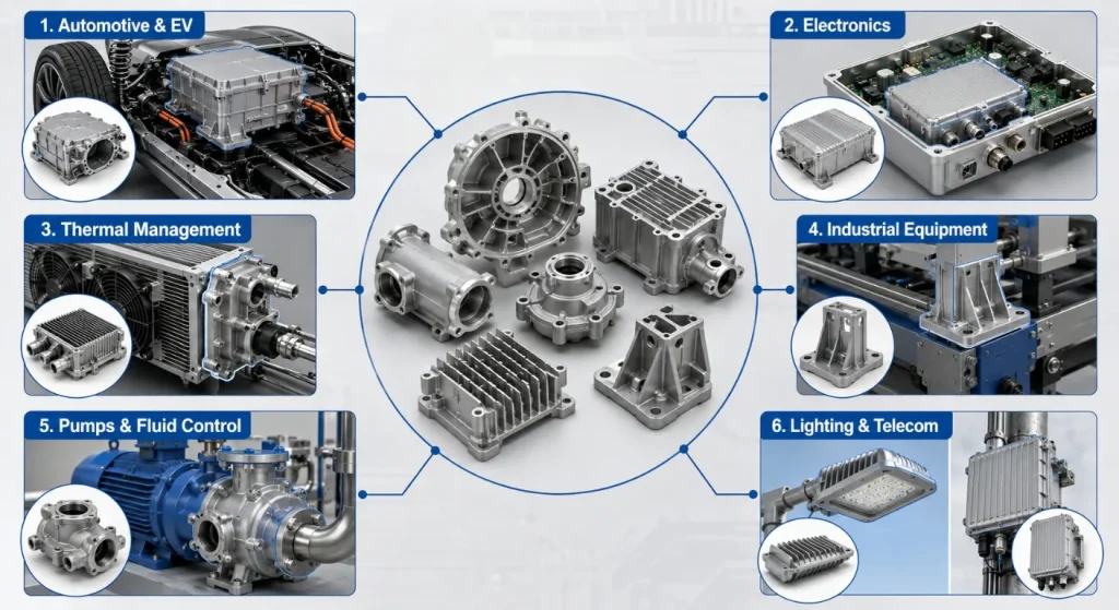
The final manufacturing route should be developed from the part function rather than from appearance alone.
Selecting an Aluminum Die Casting Alloy
The RFQ should specify an exact casting-alloy designation or ask the supplier to recommend one according to the application.
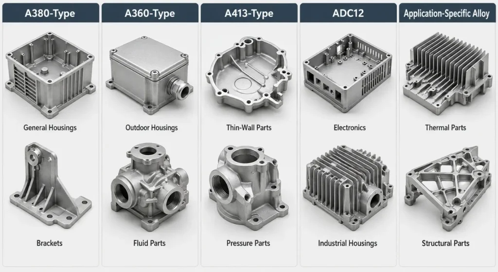
ASTM B85/B85M-25 covers aluminum-alloy die castings, while the Aluminum Association maintains registered designations and chemical-composition limits for cast aluminum alloys. A380.0, A360.0 and A413.0 are examples of registered die casting designations, but their selection should be based on the required property and process balance. (ASTM B85/B85M-25; Aluminum Association Pink Sheets)
A380-Type Alloys
A380 is a common starting point for general-purpose aluminum die cast parts. NADCA identifies it as a commonly used aluminum die casting alloy.
It may be evaluated for:
- Equipment housings
- Brackets
- Covers
- Appliance parts
- Automotive components
- General industrial castings
The alloy name alone does not define the final part performance. Wall thickness, casting conditions, porosity, service temperature, machining, and heat exposure must also be considered.
A360-Type Alloys
A360-type material may be reviewed when the project requires a different balance of corrosion performance, ductility, pressure-tightness, or mechanical behavior.
It can require different casting conditions from a general-purpose A380-type alloy. The supplier should confirm machine compatibility, tooling strategy, filling behavior, and finishing requirements before approval.
A413-Type Alloys
A413-type alloys may be considered for parts requiring good cavity filling or pressure-tight characteristics.
However, no alloy can compensate for poor wall transitions, unsuitable gate design, trapped air, inadequate venting, or an unrealistic sealing requirement.
ADC12 and Regional Specifications
ADC12 is commonly specified in projects using Japanese or Asian material systems.
It should not automatically be treated as a fully interchangeable name for A380. Chemical limits, customer specifications, supplier standards, material certificates, and applicable test requirements should be confirmed before quotation.
Application-Specific Alloys
Some projects require specialized alloys for:
- Higher thermal conductivity
- Improved ductility
- Structural applications
- Vacuum die casting
- Heat treatment
- Electrical performance
- Corrosion exposure
These materials may require different melt controls, vacuum systems, heat treatment, mold design, or mechanical testing. The commercial alloy and applicable standard should be stated clearly.
Design Custom Parts for the Die Casting Process
A CAD model that can be machined does not automatically make a suitable die casting.
NADCA recommends relatively uniform wall thickness, sufficient draft for ejection, and fillets or radii at edges and corners.
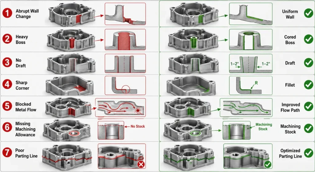
Maintain Controlled Wall Thickness
Abrupt transitions between thick and thin sections can affect:
- Metal filling
- Cooling
- Shrinkage
- Internal quality
- Surface appearance
- Dimensional stability
- Cycle consistency
Possible improvements include:
- Maintaining relatively consistent walls
- Using gradual transitions
- Coring unnecessary solid mass
- Adding ribs instead of increasing the complete wall
- Separating structural and cosmetic requirements
There is no universal minimum wall thickness for every custom aluminum die cast part. The practical limit depends on alloy, flow length, part size, gate position, machine capacity, rib structure, and acceptance requirements.
Use Ribs for Stiffness
Ribs can increase stiffness without adding excessive general wall thickness. NADCA identifies ribs as a method for adding structural support while controlling material mass.
Rib design should consider:
- Thickness
- Height
- Spacing
- Draft
- Fillet connection
- Metal flow
- Ejection
- Cosmetic appearance
Design Bosses Carefully
Bosses may support screws, inserts, bearings, locating pins, or assembly interfaces.
Large solid bosses can create isolated heavy sections. Cored bosses, ribs, fillets, and controlled wall connections may provide a more castable structure.
Bosses should also include suitable draft and access for machining, tapping, insert installation, or inspection.
Add Draft and Fillets
Surfaces parallel to the mold-opening direction generally require draft.
The required draft depends on:
- Alloy
- Surface depth
- Internal or external geometry
- Surface texture
- Ejection method
- Dimensional requirement
Fillets and radii can improve metal flow, reduce stress concentration, support ejection, and avoid fragile mold edges.
Plan Holes and Windows
Some holes can be formed with fixed cores, movable cores, or cast pins. Other holes are better drilled or reamed after casting.
Through-holes and windows can interrupt metal flow and affect ejection. NADCA notes that cross-feeders, overflows, and flash-over features may be used where the geometry blocks flow.
Plan the Parting Line and Cosmetic Surfaces
The parting line is where the two main die halves meet. Its position affects flash, appearance, ejection, trimming, slides, and dimensional relationships.
The RFQ should identify:
- Class-A or visible surfaces
- Surfaces hidden after assembly
- Acceptable ejector locations
- Acceptable parting-line locations
- Gate-removal areas
- Texture requirements
- Coating contact or rack marks
- Areas that will be machined
A poorly positioned parting line may create visible flash, complex trimming, unnecessary slides, or inconsistent relationships between functional features.
Tooling, Metal Flow, and Thermal Control
A production mold may include:
- Cover and ejector die halves
- Core and cavity inserts
- Runner and gate system
- Vents and overflows
- Slides and movable cores
- Ejector pins
- Cooling channels
- Replaceable core pins
- Trim tooling
- Sensors and standard components
The runner, gate, overflow, and vent system should be developed as one metal-flow system.
NADCA’s gating guidance connects machine constraints, runner design, gates, overflows, vents, and simulation verification rather than treating them as separate details.
Cooling circuits should create a stable and controllable mold-temperature distribution. Poor thermal balance can contribute to:
- Premature solidification
- Local hot spots
- Distortion
- Dimensional drift
- Soldering
- Surface variation
- Unstable cycle time
- Thermal fatigue
Mold-flow and thermal simulation can support engineering decisions, but physical trial casting is still required.
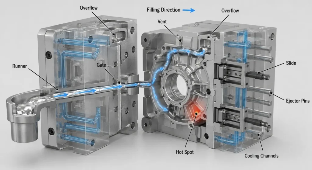
For detailed tooling information, review SunOn’s die casting mold design guide.
Secondary CNC Machining
Die casting can produce complex near-net-shape geometry, but critical interfaces may still require CNC machining.
Common operations include:
- Milling sealing surfaces
- Reaming precision bores
- Drilling holes
- Tapping threads
- Machining bearing seats
- Controlling connector locations
- Machining O-ring grooves
- Removing gate or parting-line material
The design should define:
- As-cast datums
- Machining datums
- Machining allowance
- Clamping surfaces
- Critical machined dimensions
- Surface roughness
- Final inspection condition
Parts requiring several machined faces should be reviewed for stable fixture access and datum transfer.
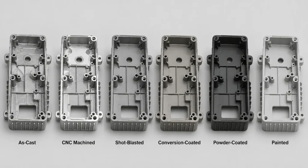
CNC machining cannot reliably correct major casting distortion, misplaced porosity, or insufficient material allowance.
Inserts and Assembly Features
Custom aluminum die cast parts may incorporate:
- Threaded inserts
- Steel sleeves
- Bushings
- Pins
- Studs
- Electrical contacts
- Seals
- Press-fit components
Inserts may be installed during casting or through a secondary assembly operation.
The decision should consider:
- Insert retention
- Thermal expansion
- Galvanic interaction
- Casting flow
- Porosity around the insert
- Positional tolerance
- Replacement and repair
- Production automation
Cast-in threads may suit some applications, while machined threads or installed inserts may be preferable for controlled thread class, repeated assembly, or higher loads.
Surface Finishing
Custom aluminum die cast parts can receive:
- Trimming and deburring
- Shot blasting
- Bead blasting
- Tumbling
- Polishing
- Powder coating
- Wet painting
- Chemical conversion coating
- Plating
- Laser marking
- Local masking
Surface finish should be selected according to:
- Corrosion exposure
- Cosmetic requirements
- Electrical grounding
- Thermal interfaces
- Wear
- Coating thickness
- Sealing
- Assembly fit
- Operating temperature
The RFQ should identify whether dimensions apply before or after finishing.
Powder coating or painting cannot reliably hide severe flow marks, cold shuts, dents, flash, or porosity exposed during polishing. Casting-quality expectations should be defined before the coating process.
For harsh environments, see SunOn’s corrosion-resistant aluminum die casting guide.
Inspection and Testing
Inspection should focus on characteristics affecting function, appearance, assembly, safety, sealing, and customer acceptance.
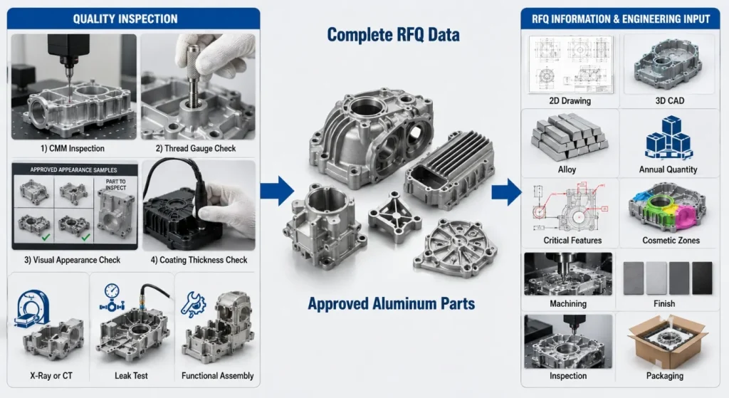
Possible controls include:
- Alloy-composition verification
- Material certificates
- First-article dimensional inspection
- CMM measurement
- Thread and bore gauges
- Flatness inspection
- Visual appearance standards
- Coating-thickness measurement
- Adhesion testing
- X-ray or CT inspection
- Leak or pressure testing
- Mechanical testing
- Functional assembly
- Packaging inspection
Not every project requires every inspection method.
X-ray or CT should be targeted toward defined internal-quality requirements rather than used as a general guarantee that a casting contains no porosity.
Pressure-tight components should define:
- Test medium
- Test pressure
- Hold time
- Acceptable leakage
- Tested quantity
- Test stage
- Reporting requirement
Die Casting vs. CNC Machining and Extrusion
Die Casting
Custom aluminum die casting may be suitable when the project requires:
- Complex integrated geometry
- Repeat production
- Thin walls and ribs
- Multiple mounting features
- Enclosures or housings
- Reduced assembly count
- Stable production tooling
CNC Machining
CNC machining may be more practical when:
- Quantities are low
- The design is changing
- Very tight local tolerances dominate
- Tooling investment is not justified
- The part is relatively simple
- Wrought-alloy properties are required
Aluminum Extrusion
Extrusion may suit components with:
- A constant cross-section
- Long linear geometry
- Rails, frames, channels, or heat sinks
- Cut-to-length and secondary machining
The most economical process depends on total lifetime cost, not only unit price.
From Drawing Review to Production
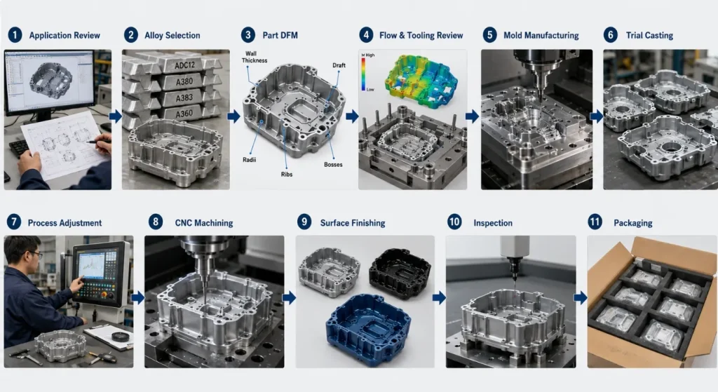
A controlled project commonly follows:
- Application Review: Confirm function, loads, environment, quantity, and appearance.
- Alloy Selection: Define the exact aluminum casting alloy and standard.
- Part DFM: Review walls, ribs, bosses, draft, fillets, holes, and machining.
- Flow and Tooling Review: Plan gates, runners, vents, overflows, slides, and cooling.
- Mold Manufacturing: Produce, heat treat, finish, and assemble the tooling.
- Trial Casting: Evaluate filling, flash, ejection, dimensions, and surface condition.
- Process Adjustment: Refine mold details and production settings.
- CNC Machining: Complete critical bores, faces, threads, and sealing features.
- Surface Finishing: Apply the required preparation, coating, or marking.
- Inspection and Testing: Verify dimensional, cosmetic, coating, and functional requirements.
- Packaging and Delivery: Protect machined, sealing, and cosmetic surfaces.
For projects with uncertain demand, low-volume aluminum die casting may support validation before full production tooling is finalized.
What to Include in an Aluminum Die Casting RFQ
Provide:
- Controlled 2D engineering drawing
- 3D CAD model
- Part function and application
- Required alloy and standard
- Annual and lifetime quantities
- Target casting machine information, if applicable
- Critical dimensions and GD&T
- Cosmetic zones
- Pressure-tight or structural requirements
- Cast-in and machined features
- Machining allowance
- Threads and inserts
- Surface finish and coating
- Corrosion requirements
- Inspection and testing
- Trial-sample requirements
- Material and process certificates
- Packaging and labeling
- Production and delivery location
SunOn’s die cast parts supplier guide provides additional factors for evaluating tooling, production, machining, finishing, and quality support.
Frequently Asked Questions
1. Which Aluminum Alloy Is Best for Custom Die Cast Parts?
A380-type material is a common starting point for many general-purpose components. A360, A413, ADC12, structural, high-conductivity, and other alloys should be evaluated according to corrosion, strength, pressure-tightness, ductility, thermal performance, and process requirements.
2. What Is the Minimum Order Quantity for Aluminum Die Casting?
There is no universal minimum quantity. Tooling investment, part size, complexity, cavity count, machining, finish, and expected lifetime demand determine whether production die casting, bridge tooling, or CNC machining is more economical.
3. Can Aluminum Die Cast Parts Be Pressure-Tight?
Yes, some parts can be designed and produced for pressure or leak requirements. Alloy, metal flow, vacuum strategy, wall transitions, machining location, sealing design, test pressure, hold time, and acceptance criteria must be defined together.
4. Can Tight Tolerances Be Produced Directly by Die Casting?
Some dimensions may be controlled in the as-cast condition, while bearing seats, sealing faces, precision bores, threads, and closely related features may require CNC machining. Tolerances should be assigned according to function and verified after all relevant processing.
5. Which Surface Finishes Are Available for Aluminum Die Cast Parts?
Options may include shot blasting, bead blasting, polishing, conversion coating, powder coating, painting, plating, and laser marking. Finish selection should consider alloy, porosity, cosmetic zones, corrosion exposure, coating thickness, grounding, and masking.
6. What Information Is Needed for an Aluminum Die Casting Quote?
Provide 2D and 3D files, alloy, annual quantity, lifetime demand, critical dimensions, cosmetic zones, machining, inserts, finish, testing, inspection, packaging, and delivery requirements. Pressure-tight and structural requirements should be identified before tooling quotation.
Conclusion
Reliable custom aluminum die cast parts begin with a defined application, exact alloy, castable geometry, and clear production requirements.
Walls, ribs, bosses, draft, parting lines, gates, vents, cooling, ejection, machining datums, coatings, inspection, and testing should be planned as one manufacturing system.
Customization should not mean adding complexity without a functional reason. It should mean adapting the material, tooling, manufacturing process, secondary operations, and quality plan to the requirements of the finished assembly.
To request a project review, contact SunOn with your drawings, CAD model, alloy, quantities, critical dimensions, cosmetic zones, machining, finish, inspection, and testing requirements.
