


Family Mold Injection Molding: Design, Balance, and RFQ Guide
Family mold injection molding produces two or more different but related plastic parts in one molding cycle.
A common example is a product housing with separate front and rear covers. Other examples include left- and right-hand components, matched clips and brackets, or several parts required to assemble one product.
The main attraction is clear: related components can share one mold base, one molding machine, and one production cycle.
However, combining different parts into one tool creates engineering challenges that do not exist in a standard multi-cavity mold containing identical cavities. Each part may have a different volume, flow length, wall thickness, gate requirement, cooling time, shrinkage behavior, and annual demand.
For engineers and technical buyers, the correct question is not simply:
Can these parts fit inside one mold?
A better question is:
Can these parts be molded together through a stable process window while maintaining the required quality and production ratio?
SunOn supports custom plastic injection molding projects from part DFM and family-mold feasibility review through mold design, mold-flow analysis, trial molding, validation, and repeat production.
Family Mold Injection Molding at a Glance
| Project Condition | Family Mold Direction |
|---|---|
| Related parts use the same resin | Potentially suitable |
| Parts use the same color | Potentially suitable |
| One of each part is required per assembly | Strong production-ratio match |
| Part volumes and flow resistance are similar | Easier to balance |
| Cooling times are reasonably close | More stable shared cycle |
| Parts require different materials | Usually use separate or multi-shot tooling |
| Parts require different colors per cycle | Standard family molding is usually unsuitable |
| Annual demand differs significantly | Inventory imbalance risk |
| One part changes frequently | Shared-tool revision risk |
| One component has strict CTQ requirements | Separate tooling may provide better control |
What Is a Family Mold?
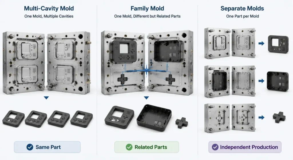
A family mold is a multi-cavity injection mold in which the cavities form different components of the same finished product or related product set. This differs from a conventional multi-cavity mold, where every cavity normally produces an identical part. Mold-Masters uses the same definition in its hot-runner technical documentation.
A family mold may produce:
- Front and rear enclosure covers
- Left- and right-hand components
- A lid and matching base
- Several internal brackets
- Buttons and supporting components
- Related clips and retainers
- Product-kit components
- Matched assembly parts
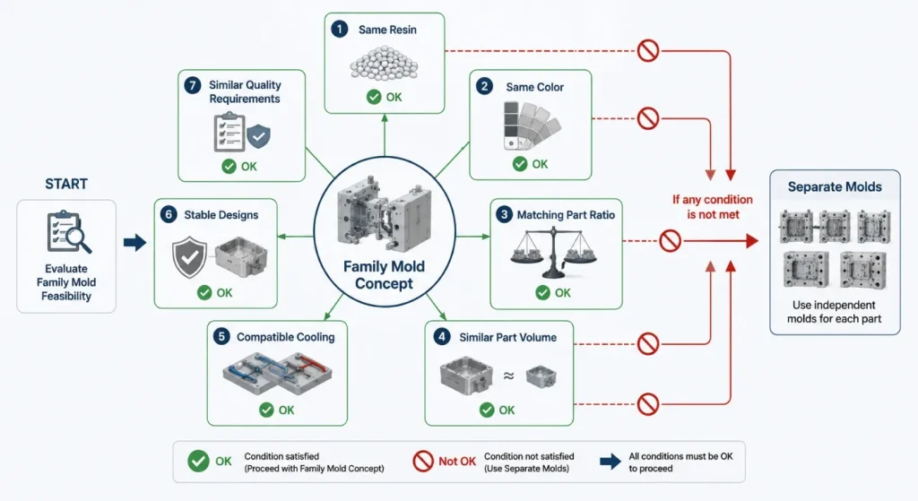
Family molds generally use one resin and one color during each molding cycle because all cavities are fed by the same injection unit and melt-delivery system.
When related parts require different materials, colors, or incompatible molding temperatures, separate molds, insert molding, overmolding, or 2K injection molding may be more suitable.
Family Mold vs. Multi-Cavity Mold
These terms should not be used interchangeably.
| Tool Type | Cavities | Output per Cycle | Main Objective |
|---|---|---|---|
| Single-cavity mold | One cavity | One part | Development, low demand, or large parts |
| Multi-cavity mold | Several identical cavities | Several copies of one part | Higher output |
| Family mold | Several different cavities | A related set of parts | Shared tooling and synchronized production |
| Multi-shot mold | Multiple materials or shots | One integrated multi-material part | Material or color integration |
A multi-cavity mold is usually easier to balance because the cavities, gates, filling volumes, and cooling requirements are substantially similar.
A family mold contains different part geometries. The melt may naturally reach one cavity earlier than another, which increases the risk of short shots in one part and overpacking or flash in another.
SunOn’s injection mold types guide provides a broader comparison of single-cavity, multi-cavity, family, stack, insert, and multi-material tooling.
When Is a Family Mold a Good Choice?
Parts Belong to the Same Assembly
Family tooling is most practical when the molded parts are consumed together.
For example, if every finished product requires one top cover and one bottom cover, producing one of each per molding cycle can simplify:
- Production scheduling
- Assembly-kit preparation
- Inventory management
- Color consistency
- Batch traceability
Parts Use the Same Material and Color
All parts should normally be compatible with the same:
- Resin family
- Material grade
- Filler content
- Color
- Drying requirement
- Melt temperature
- Mold temperature
- Packing conditions
- Regulatory documentation
Using similar-looking but technically different materials in a standard family mold is not practical when they require separate processing conditions.
Production Ratios Match
A family mold produces a fixed part ratio in every cycle.
A mold containing one cavity for Part A and one cavity for Part B always produces them at a 1:1 ratio. A mold containing two Part A cavities and one Part B cavity produces a 2:1 ratio.
The cavity arrangement should reflect actual assembly consumption and forecast demand.
If the product requires one Part A but four Part B components, a 1:1 mold creates excess Part A inventory unless the cavity count is adjusted.
Parts Have Compatible Cycle Requirements
The molding cycle is generally controlled by the slowest-cooling or most demanding component.
A thin cover and a heavy structural bracket may not be a good combination because the cover may be ready for ejection long before the bracket has cooled sufficiently.
The shared cycle should be evaluated for:
- Filling time
- Packing time
- Cooling time
- Ejection temperature
- Part stiffness
- Dimensional stabilization
When Should Parts Use Separate Molds?
Family tooling should not be selected only because its initial quotation is lower.
Separate molds may be more appropriate when:
- Parts use different materials
- Different colors are needed
- Volumes or replacement rates differ
- Wall thicknesses vary substantially
- One part requires much longer cooling
- One component has frequent design revisions
- Parts require very different surface finishes
- One cavity has safety-critical dimensions
- Gate requirements conflict
- Machine size becomes unnecessarily large
- One part may be discontinued before the others
A shared mold also creates shared downtime. Damage, maintenance, or engineering changes affecting one cavity can stop production of every component in the tool.
The Main Engineering Challenge: Filling Balance
Autodesk Moldflow states that runners must be balanced in molds containing multiple cavities, including family molds. Runner balancing adjusts the delivery system so the cavities fill at suitable rates.
Family-mold balance is difficult because the cavities may differ in:
- Part volume
- Projected area
- Wall thickness
- Flow length
- Gate location
- Geometry
- Pressure requirement
- Material orientation
- Venting demand
An unbalanced feed system can produce hesitation, incomplete filling, overpacking, flash, sink, warpage, or inconsistent shrinkage. Autodesk specifically identifies hesitation, underflow, and overpacking as risks in unbalanced family-mold runner systems.
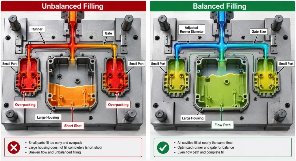
The objective is not necessarily to make every runner geometrically identical. It is to deliver the required melt volume and pressure to each cavity so the different parts fill and pack within a usable process window.
Runner and Gate Strategies
Naturally Balanced Runner
A naturally balanced runner uses similar flow lengths and geometrically symmetrical branches.
This approach is easier with identical cavities. It may be impossible in a family mold because different parts require different melt volumes and cavity positions.
Artificially Balanced Runner
Runner diameters, lengths, or restrictions can be adjusted to change the flow resistance to individual cavities.
This method may help synchronize filling, but overly small runner sections can increase pressure loss, shear, freeze-off, or packing difficulty.
Gate-Size Adjustment
Gate dimensions can be modified to control how quickly resin enters each cavity.
However, using a very small gate to restrict one part may affect:
- Shear rate
- Gate freeze time
- Packing
- Gate vestige
- Local stress
- Appearance
Runner and gate adjustments should therefore be evaluated together rather than using gate size as the only balancing tool.
Hot Runner and Valve Gates
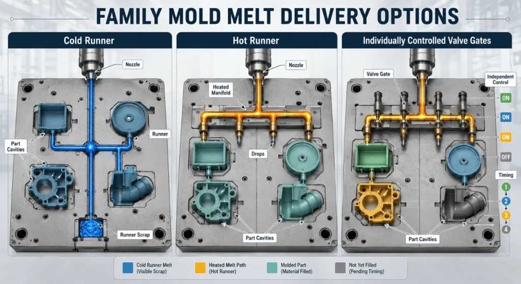
A hot-runner system can reduce cold-runner scrap and provide more control over cavity filling.
Individually controlled valve gates can adjust the opening timing and sequence for different cavities. Mold-Masters describes servo valve-gate systems that control valve-pin position, speed, timing, and sequence, which can help manage demanding flow conditions.
Hot runners and valve gates add:
- Tooling investment
- Temperature-control requirements
- Maintenance
- Start-up procedures
- Spare-component needs
- Process-development complexity
They should be selected when their process and material benefits justify the additional system cost.
Use Mold-Flow Analysis Before Cutting Steel
Mold-flow analysis can compare:
- Cavity filling time
- Pressure at the flow front
- Runner balance
- Gate location
- Weld lines
- Air traps
- Shear rate
- Clamp-force demand
- Packing behavior
- Cooling
- Warpage
Autodesk describes the feed-system objective as creating balanced flow so the parts in a mold fill at an appropriate rate.
The simulation should use realistic inputs for:
- Exact resin grade
- Material viscosity
- Part thickness
- Runner dimensions
- Gate geometry
- Mold temperature
- Melt temperature
- Machine limits
- Injection profile
Simulation does not replace mold trials. It helps identify risk before steel is cut and provides a stronger starting point for runner, gate, cooling, and process development.
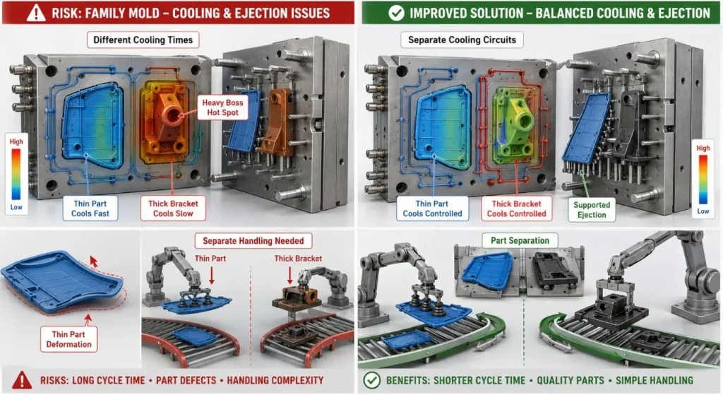
Cooling Must Work for Every Cavity
Different parts can have different cooling requirements because of their volume, wall thickness, ribs, bosses, inserts, and local mass.
A family mold should avoid allowing one heavy part to determine an unnecessarily long cycle for every smaller component.
Cooling design should consider:
- Separate cavity cooling circuits
- Core cooling
- Baffles or bubblers
- Local hot spots
- Water-flow balance
- Mold-temperature zones
- Part ejection temperature
- Cooling-channel maintenance
The cooling system should also be adjustable during mold trials where practical.
Ejection, Handling, and Part Separation
Different family-mold parts may require different ejection methods.
Possible systems include:
- Ejector pins
- Ejector sleeves
- Stripper plates
- Blade ejectors
- Air assist
- Robotic part removal
Ejection should account for:
- Part shrinkage
- Core retention
- Cosmetic surfaces
- Thin walls
- Snap features
- Deep ribs
- Part orientation
- Automated handling
The production cell must also separate and identify the different molded components.
Options include:
- Robot grippers with separate nests
- Conveyor separation
- Cavity identification
- Vision inspection
- Part-count verification
- Assembly-kit packaging
Design Changes Create Shared-Tool Risk
A family mold links several part designs to one mold base and one production process.
Changing one component may require:
- Cavity insert modification
- Runner rebalancing
- Gate changes
- Cooling changes
- New mold-flow analysis
- New molding trials
- Revalidation of all cavities
The design team should review product maturity before choosing family tooling.
Parts likely to change independently may be safer in separate molds, even when the initial mold investment is higher.
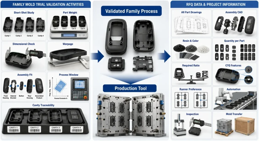
Quality Control and Mold Acceptance
Family-mold validation should assess each cavity separately and the combined molding process.
The acceptance plan may include:
- First-article inspection by cavity
- Cavity identification
- Dimensional reports
- Appearance standards
- Part-weight monitoring
- Short-shot studies
- Process-window trials
- Packing and cooling evaluation
- Warpage measurement
- Assembly-fit checks
- Cavity-to-cavity traceability
- Capability studies
- Automated part-count verification
A passing result for one part does not prove that every cavity has an equally stable process.
The trial should demonstrate that all family members can meet their requirements under the same approved molding conditions.
Family Mold Cost Should Be Evaluated by Total Production Risk
A family mold may reduce:
- Number of mold bases
- Initial tooling investment
- Mold-storage space
- Mold-change frequency
- Assembly-set inventory
- Separate molding-machine demand
It may increase:
- Mold-design complexity
- Flow-analysis requirements
- Trial and tuning time
- Hot-runner investment
- Maintenance impact
- Shared downtime
- Engineering-change risk
- Scrap when one cavity fails
- Production imbalance when demand changes
The decision should compare total lifetime cost rather than only the first tooling quotation.
SunOn’s injection molding cost guide also discusses family molds as one possible cost strategy when related components have compatible size and material requirements.
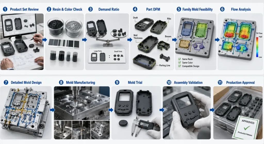
From Feasibility Review to Production
A controlled family mold project commonly follows:
- Product-Set Review: Confirm which parts belong together and their assembly ratio.
- Material Review: Verify that the parts use the same resin, color, and molding conditions.
- Demand Review: Compare annual quantities and replacement rates.
- Part DFM: Review walls, draft, ribs, bosses, undercuts, cosmetics, and ejection.
- Family-Mold Feasibility: Compare part volume, flow resistance, cooling, and quality requirements.
- Runner and Gate Analysis: Balance the feed system and evaluate hot- or cold-runner options.
- Cooling and Ejection Design: Develop independent cavity controls where needed.
- Mold Manufacturing: Complete CNC, EDM, fitting, polishing, assembly, and inspection.
- Mold Trials: Evaluate each cavity and the combined process window.
- Assembly Validation: Confirm that the produced family parts fit and function together.
- Production Approval: Finalize process parameters, inspection, maintenance, and traceability.
SunOn’s custom plastic injection mould service supports mold manufacturing and production planning for drawing-based plastic-component projects.
What to Include in a Family Mold RFQ
Provide:
- 2D drawings for every component
- 3D CAD files for every component
- Product assembly model
- Exact resin grade
- Color and appearance requirements
- Annual quantity for each part
- Required part ratio
- Product-lifetime demand
- Critical dimensions and CTQ features
- Surface textures and cosmetic zones
- Gate restrictions
- Insert and undercut requirements
- Assembly-fit requirements
- Hot- or cold-runner preference
- Machine information, where specified
- Automation and part-separation requirements
- Inspection and capability requirements
- Mold-transfer and maintenance requirements
- Spare-insert requirements
- Packaging and delivery needs
A complete RFQ should allow the mold supplier to compare a family mold with separate molds rather than assuming the family concept is already approved.
Conclusion
Family mold injection molding can reduce tooling count and produce related assembly components in synchronized quantities.
Its value depends on whether the parts genuinely share compatible material, color, flow, cooling, ejection, quality, and production-ratio requirements.
The most important engineering challenge is not fitting several cavities into one mold base. It is establishing a stable process in which every different cavity fills, packs, cools, ejects, and passes inspection under the same molding cycle.
When part volumes, demand, materials, or quality requirements differ significantly, separate molds may provide lower lifetime risk despite a higher initial investment.
To request a family-mold feasibility review, contact SunOn with all part files, the product assembly, resin, quantities, required production ratio, quality requirements, and tooling expectations.
Frequently Asked Questions About Family Mold Injection Molding
1. What Is the Difference Between a Family Mold and a Multi-Cavity Mold?
A family mold produces different related parts in one cycle, while a multi-cavity mold normally produces several identical copies of one part. Family molds require more attention to runner balance, cooling, ejection, and production ratios.
2. Can Different Materials Be Used in One Family Mold?
A standard single-shot family mold normally uses the same resin and color for every cavity. Parts requiring different materials or incompatible processing temperatures usually need separate molds or a multi-shot molding process.
3. Why Are Family Molds Difficult to Balance?
Each part can have a different volume, flow length, wall thickness, gate requirement, and packing demand. Without a balanced feed system, one cavity may short-shot while another becomes overpacked or flashes.
4. Can a Family Mold Use a Hot-Runner System?
Yes. Hot runners can reduce runner waste and valve gates can provide additional control over individual cavity filling. The higher tooling cost, maintenance, material behavior, and production volume should be evaluated before selection.
5. When Are Separate Molds Better Than a Family Mold?
Separate molds are usually safer when parts use different materials, have different demand ratios, require very different cooling times, or are likely to change independently. They also allow one component to continue production while another tool is maintained or modified.
6. What Information Is Needed for a Family Mold Quote?
Provide every component drawing, the complete assembly, resin, color, annual quantity per part, production ratio, CTQ features, cosmetic requirements, automation, inspection, and mold-transfer needs. The supplier should be allowed to compare family and separate tooling options.
