


Vapor Chamber vs. Heat Sink: Comparing Cooling Technologies | SunOn
The vapor chamber vs heat sink comparison is not always a choice between two separate cooling products. A conventional heat sink uses a solid metal base and fins to conduct heat away from a component and release it into the surrounding air. A vapor chamber mainly spreads concentrated heat across a wider surface. In higher-performance assemblies, the vapor chamber often becomes the base underneath the heat-sink fins.
The right option depends on where the thermal bottleneck occurs. A conventional heat sink may be enough when its base can spread heat effectively and sufficient airflow is available. A vapor-chamber-enhanced heat sink becomes more useful when a small, high-power component creates a concentrated hot spot beneath a much larger fin area. When the main problem is insufficient heat rejection rather than poor spreading, liquid cooling may be the more appropriate direction.
Vapor Chamber vs. Heat Sink at a Glance
| Criterion | Conventional Heat Sink | Vapor-Chamber-Enhanced Heat Sink |
|---|---|---|
| Primary function | Conducts heat and rejects it to the air | Spreads heat across the base before fins reject it |
| Main mechanism | Solid conduction and convection | Phase-change heat spreading and convection |
| Best heat-source profile | Moderate or relatively distributed heat source | Small, concentrated, high-power heat source |
| Base temperature uniformity | May develop a large temperature gradient | Usually provides a more uniform base temperature |
| Hot-spot control | Moderate | Stronger when spreading resistance is the problem |
| Airflow dependence | High | Still high because the fins must reject the heat |
| Mechanical complexity | Lower | Higher |
| Cost | Usually lower | Usually higher |
| Manufacturing options | Extrusion, die casting, CNC machining, skiving and bonded fins | Vapor chamber integrated with a compatible fin structure |
| Typical selection trigger | Adequate thermal performance at lower cost | Tight thermal budget and excessive base temperature variation |
These are general tendencies, not guaranteed performance values. The result also depends on heat-source area, power density, base dimensions, thermal interface material, mounting pressure, fin geometry, airflow and ambient temperature.
How Does a Vapor Chamber Work?
A vapor chamber is a sealed, flat heat spreader containing a small amount of working fluid and an internal return structure. Its operating cycle has several stages:
- Heat enters the evaporator region directly above the component.
- The working fluid absorbs energy and turns into vapor.
- The vapor moves through the internal cavity toward cooler regions.
- It condenses and releases heat across a wider surface.
- The wick structure returns the liquid to the heat-source area through capillary action.
This two-phase process can move heat laterally across the chamber more evenly than a conventional solid base. The result is a more isothermal surface, meaning the temperature difference between the center and outer areas can be reduced.
A vapor chamber is primarily a heat spreader. It still needs another path for releasing heat. In an air-cooled assembly, that path normally consists of fins and natural or forced airflow.
Main Advantages of a Vapor Chamber
- Spreads heat efficiently across a large planar area
- Reduces concentrated hot spots
- Creates a more uniform heat-sink base temperature
- Allows fins farther from the heat source to contribute more effectively
- Supports compact systems with high local power density
- Can improve heat distribution when one small component sits beneath a large fin stack
Main Limitations of a Vapor Chamber
- Higher cost than a basic solid aluminum base
- More complex construction and integration
- Mechanical pressure and deformation must be controlled
- Performance depends on the chamber geometry and wick design
- Capillary, vapor-flow and dryout limits still apply
- Orientation may affect some designs
- It does not solve insufficient fin area or poor airflow by itself
Processes such as wick sintering and vacuum sealing are part of vapor-chamber production, but they should be evaluated as specialist manufacturing capabilities. They are not confirmed SunOn production services.
How Does a Conventional Heat Sink Work?
A conventional heat sink transfers heat through a solid aluminum, copper or hybrid structure. Heat first moves from the electronic component through a thermal interface material into the heat-sink base. It then spreads through the base and travels into the fins. The fins increase the available surface area, allowing heat to move into the surrounding air through convection.
Natural-convection heat sinks depend on normal air movement caused by temperature differences. Forced-convection designs use a fan or blower to increase airflow and improve heat rejection.
Material, base thickness, contact flatness, fin spacing, airflow direction and mounting pressure all influence performance. SunOn’s guide to how heat sinks work and are manufactured provides additional detail on common materials, structures and production methods.
Main Advantages of a Conventional Heat Sink
- Lower cost and simpler construction
- Broad material and manufacturing options
- Suitable for many moderate-power applications
- Easier to customize with mounting holes, channels and enclosure features
- Scalable from prototypes to mass production
- Available through CNC machining, extrusion, skiving, bonding and die casting
- Generally easier to inspect and integrate mechanically
Main Limitations of a Conventional Heat Sink
- A small heat source can create a strong temperature gradient across a large base
- Fins far from the heat source may remain cooler and contribute less
- Thick copper bases improve conduction but add weight and cost
- Increasing base thickness can create packaging and weight problems
- Higher fin density may restrict airflow rather than improve cooling
- Performance may become spreading-limited before the full fin area is used
Heat Spreading vs. Heat Rejection: The Most Important Difference
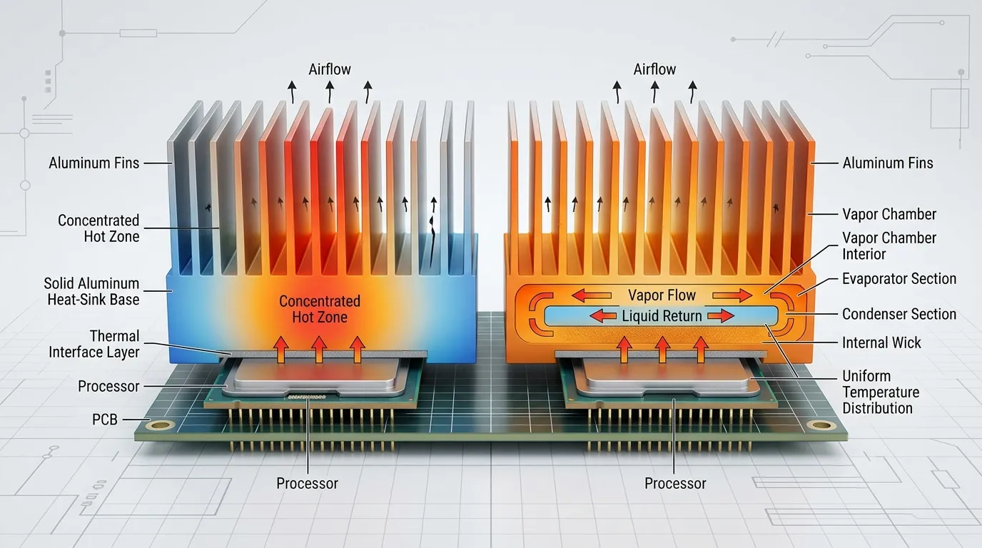
The complete thermal path can be simplified as:
Component → thermal interface material → heat-sink base or vapor chamber → fins → airflow → ambient air
Each stage adds thermal resistance.
Interface resistance appears between the component and cooling surface. Spreading resistance develops as heat moves from a small source into a larger base. Transport resistance describes movement through the cooling structure. Rejection resistance occurs when the fins transfer heat into the surrounding air.
A vapor chamber mainly reduces spreading and transport resistance. It cannot automatically correct a thick or poorly applied thermal interface material, uneven mounting pressure, insufficient fin surface area or restricted airflow.
This distinction is critical. A vapor chamber may create a more uniform fin-base temperature, but the assembly can still overheat if the fan cannot move enough air or if the hot exhaust air remains trapped inside the enclosure.
Head-to-Head Comparison by Decision Criterion
Hot-Spot Control and Temperature Uniformity
A conventional heat sink often performs well when the heat source covers a meaningful portion of the base. The heat does not need to travel far laterally before reaching the fins.
The situation changes when a small CPU, GPU, ASIC or power device sits beneath a much larger heat sink. Heat concentrates near the center, while outer sections of the base remain cooler. This increases spreading resistance and leaves part of the fin area underused.
A vapor chamber can distribute that concentrated energy across more of the base. More uniform base temperature does not create additional cooling capacity by itself, but it can help the existing fin area work more effectively.
Total Thermal Resistance
Lower spreading resistance does not always mean lower component-to-ambient temperature.
The complete assembly may still be limited by:
- Poor thermal interface contact
- Inconsistent mounting pressure
- Inadequate fin area
- Low airflow
- Excessive airflow pressure drop
- High ambient temperature
- Recirculation of hot exhaust air
Performance data should therefore identify the measurement boundary. Source-to-base resistance and source-to-ambient resistance describe different parts of the thermal path and should not be compared as though they were the same value.
Size, Weight and Packaging
Aluminum heat sinks provide a practical balance of weight, cost and thermal performance. Copper improves solid conduction but is heavier and more expensive.
A vapor chamber may improve planar spreading without requiring a very thick solid copper base. This can be useful in low-profile systems, although the chamber still needs appropriate structural support and integration with the fin stack.
Mechanical design remains important. Mounting loads, screw locations, flatness requirements and enclosure constraints must be considered before selecting either architecture.
Cost and Manufacturing Complexity
Conventional heat sinks support several established production routes.
CNC machining works well for prototypes, low volumes and complex mounting features. Skiving can create dense fins from a single metal block. Extrusion is efficient for constant cross-sections. Die-cast heat sinks for high-volume designs can combine fins, mounting features and housing geometry in one component.
Vapor-chamber assemblies introduce additional production and integration requirements. Chamber construction, sealing, internal fluid control, bonding and structural protection increase complexity. The additional cost is normally justified only when conventional solid-base spreading cannot meet the thermal target.
Reliability and Validation
Both options should be evaluated under realistic operating conditions.
Important validation factors include:
- Maximum and typical heat load
- Heat-source contact area
- Ambient temperature
- Airflow rate and direction
- Thermal interface material
- Mounting pressure
- Base flatness
- Product orientation
- Thermal cycling
- Bond quality
- Measurement location
For vapor chambers, leak integrity, structural stability and operating limits also matter. Supplier data should clearly state the test conditions instead of presenting one conductivity or resistance value without context.
When Should You Choose a Conventional Heat Sink?
A conventional heat sink is usually the practical choice when:
- Heat density is moderate
- The source occupies a reasonable portion of the base
- Available airflow is sufficient
- The thermal budget is not extremely tight
- Cost and mechanical simplicity are priorities
- An aluminum or copper base already meets the temperature target
- The design requires straightforward high-volume manufacturing
- Mounting features or enclosure functions need to be integrated into the part
A conventional design should not be rejected simply because vapor chambers offer better spreading in some applications. If spreading resistance is already low, adding a vapor chamber may increase cost without producing a meaningful system-level improvement.
When Should You Evaluate a Vapor-Chamber Heat Sink?
A vapor-chamber-enhanced heat sink deserves evaluation when:
- A small heat source sits beneath a much larger fin footprint
- The component develops a strong central hot spot
- Temperature varies significantly across the existing base
- The allowable temperature rise is limited
- Product height is tightly constrained
- Multiple compact heat sources need a more uniform base
- Increasing airflow or fin area is difficult
- A thick copper base adds too much weight
- Outer sections of the fin stack remain noticeably cooler than the center
The key question is whether the system is spreading-limited. High total wattage alone does not prove that a vapor chamber is necessary. Source size, heat flux and the temperature distribution across the base provide better evidence.
When Is Neither Option Enough?
A vapor chamber can distribute heat more effectively, but it cannot provide unlimited air-cooling capacity. If the fin array and available airflow cannot release the required heat, improving the base alone will not solve the problem.
A cold plate or another liquid-cooled architecture may be more appropriate when:
- Airflow is severely restricted
- Fan noise limits prevent higher airflow
- Ambient temperature is high
- Heat rejection exceeds the practical capacity of the available fin volume
- Rack or enclosure density is too high
- The system remains rejection-limited after improving the interface, base and fins
This decision belongs within the broader cold plate versus heat sink comparison. It should be based on the entire cooling system, including pumps, coolant paths, radiators, manifolds and maintenance requirements, rather than only the component-level spreader.
Three Practical Selection Examples
Broad LED or Power Module With Moderate Heat Density
A large LED board or power module may distribute heat across much of its mounting surface. If the heat load is moderate and airflow is available, a conventional aluminum heat sink may provide sufficient spreading and rejection. A die-cast design can also be practical when the part requires integrated mounting or enclosure features at production volume.
Compact CPU, GPU or ASIC Under a Large Fin Stack
A compact processor can concentrate heat in the center of a much larger heat sink. A solid base may develop a high central temperature while the outer fins remain underused. A vapor-chamber-enhanced heat sink may reduce that temperature gradient and engage more of the fin area.
High-Power System With Restricted Airflow
When airflow is already the dominant limitation, replacing a solid base with a vapor chamber may improve temperature uniformity without reducing the final component temperature enough. The engineering team should first determine whether the system is rejection-limited. Liquid cooling may offer a more meaningful improvement.
Common Selection Mistakes
- Treating a vapor chamber as a complete heat-rejection system
- Assuming it always replaces the heat sink
- Comparing effective conductivity values without test conditions
- Considering total wattage but ignoring source size and heat flux
- Ignoring the thermal interface material
- Overlooking base flatness and mounting pressure
- Assuming more fins always improve cooling
- Ignoring airflow pressure drop and hot-air recirculation
- Selecting copper only because its bulk conductivity is higher
- Comparing source-to-base and source-to-ambient resistance directly
- Treating simulation results as validated production performance
- Claiming vapor-chamber manufacturing capability without supporting evidence
Questions to Ask Before Choosing
Before selecting a cooling architecture, define the operating conditions clearly:
- What are the maximum and typical heat loads?
- What is the heat-source contact area?
- What is the resulting power density?
- What is the maximum allowable component temperature?
- What is the highest expected ambient temperature?
- How much airflow is available?
- What are the heat-sink footprint and height limits?
- How large is the temperature gradient across the current base?
- Which thermal interface material will be used?
- What mounting pressure can the assembly support?
- Does the product operate in different orientations?
- Is fan noise limited?
- What prototype and production quantities are expected?
- Is the reported performance measured source-to-base or source-to-ambient?
These inputs make it easier to identify whether the main issue is interface resistance, spreading resistance or final heat rejection.
SunOn’s Heat-Sink Manufacturing Perspective
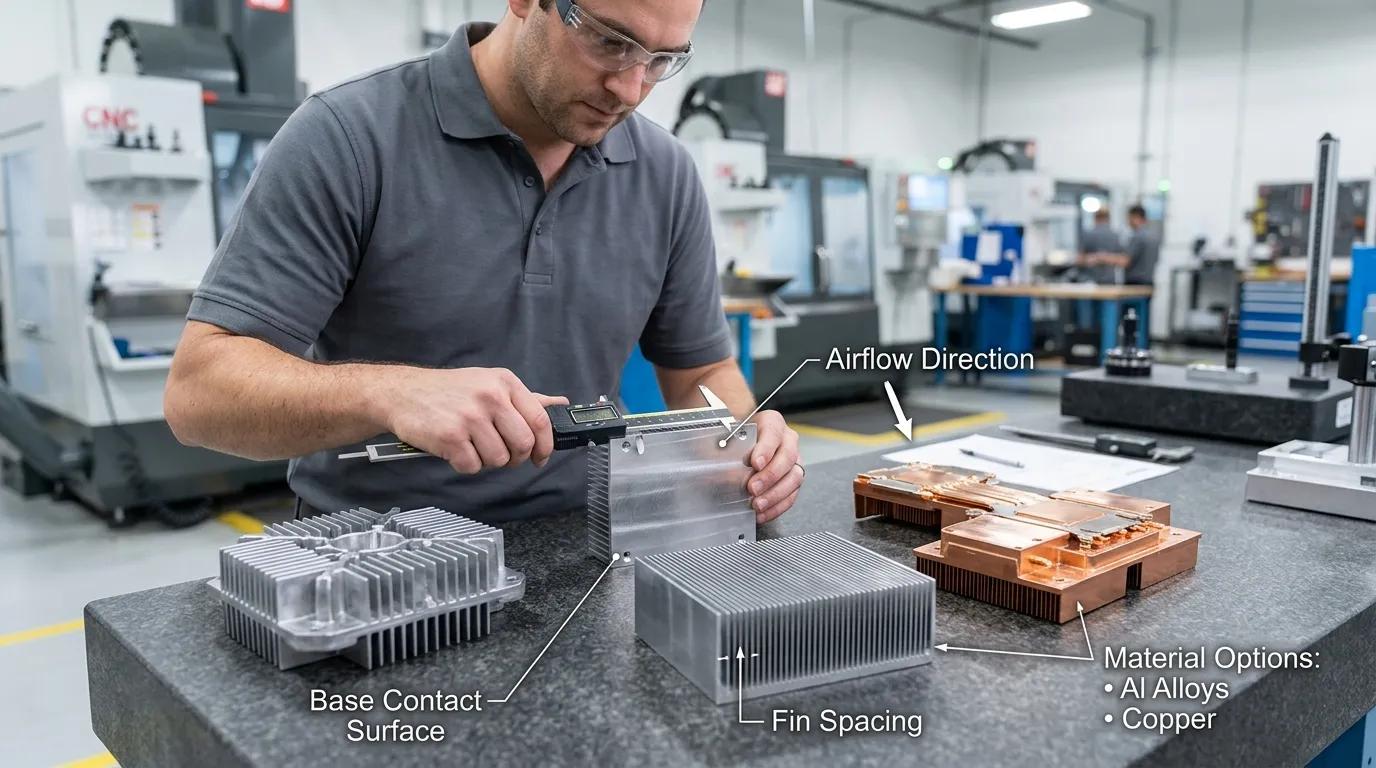
Cooling performance must be translated into a part that can be manufactured, assembled and inspected consistently.
Relevant heat-sink considerations include:
- Aluminum, copper or hybrid material selection
- CNC machining for prototypes and precise mounting features
- Die casting for integrated high-volume components
- Skived or machined fin structures for demanding air-cooled designs
- Base flatness and contact-surface machining
- Fin thickness, spacing and airflow direction
- Threaded holes, clips and mounting points
- Surface finishing and corrosion protection
- Prototype validation before production tooling
- DFM review for cost, tolerances and production stability
SunOn’s role in this comparison is tied to confirmed heat-sink design and manufacturing considerations. Vapor-chamber processes such as wick sintering, fluid charging and vacuum sealing should not be presented as SunOn services without separate capability verification.
Final Decision Summary
Use the following sequence before choosing between a conventional heat sink and a vapor-chamber-enhanced design:
- Identify the maximum heat load and heat-source area.
- Check the thermal interface, base flatness and mounting pressure.
- Determine whether the existing base has excessive spreading resistance.
- Confirm whether the fins and airflow can reject the total heat.
- Choose a conventional heat sink when solid conduction is adequate.
- Evaluate a vapor chamber when concentrated heat creates a large base temperature gradient.
- Consider a cold plate when air-side heat rejection is the main limitation.
- Validate the final assembly under real operating conditions.
| Main Thermal Condition | Likely Direction |
|---|---|
| Moderate heat density and adequate airflow | Conventional heat sink |
| Small hot source beneath a large fin area | Vapor-chamber-enhanced heat sink |
| Poor TIM contact or mounting | Correct the interface first |
| Fin or airflow capacity is insufficient | Improve air-side design or consider liquid cooling |
| High-volume part with integrated features | Evaluate die casting or another scalable heat-sink process |
Frequently Asked Questions
Is a vapor chamber better than a heat sink?
Not in every application. A vapor chamber offers stronger planar heat spreading, while a complete heat sink provides the fins and airflow path required to reject heat. A conventional heat sink is often sufficient when power density is moderate and its base spreads heat effectively.
Can a vapor chamber replace a heat sink?
Usually not by itself. A vapor chamber spreads heat but still needs a surface or cooling system that releases the heat. In many products, it replaces the solid base of a heat sink rather than replacing the entire heat sink.
Does a vapor chamber need fins or a fan?
For air-cooled electronics, it normally needs fins, and many higher-power designs also require a fan. The vapor chamber distributes heat across the base, while the fins and airflow transfer that heat into the surrounding air.
Is a vapor chamber better than a copper heat sink?
A vapor chamber may provide better temperature uniformity across a large area, especially when heat enters through a small source. A solid copper base is simpler and may be sufficient when the spreading distance is limited. The better option depends on weight, cost, source size and thermal targets.
When should a vapor-chamber heat sink be used?
It should be considered when a compact, high-power component creates a concentrated hot spot, the existing base has a large temperature gradient, and sufficient fin area and airflow are still available to reject the heat.
When is a cold plate better than a vapor chamber?
A cold plate becomes more suitable when the main limitation is total heat rejection, airflow is restricted, acoustic limits prevent higher fan speed, or the required heat load exceeds the practical capacity of the available air-cooled fin volume.
Evaluating a custom heat-sink design? Share your heat load, source dimensions, available space, airflow, mounting requirements and production volume with SunOn to discuss a practical, manufacturable heat-sink approach.
