
How to Design Parts for Silicone Rubber Molding Process: The 2026 Engineering Guide
SunOn Industrial Group Limited is a premier global manufacturer specializing in custom silicone and plastic injection molding. With over 1,000 skilled employees and a track record of exporting 95% of our precision molds to the US, Germany, and Australia, we provide the technical expertise required for complex flexible silicone parts for dynamic applications.
Essential Geometry: Designing for the "Flex"
Designing for silicone rubber molding requires understanding material elasticity and flow. Unlike rigid plastics, silicone allows for thinner walls (down to 0.25mm) and undercuts. However, maintaining a nominal wall thickness of 1.5mm to 3.0mm is critical to ensure uniform curing, prevent air traps, and maintain structural integrity during the high-pressure injection or compression process.
In our experience at SunOn, the relationship between wall thickness and durometer (hardness) is the most common point of failure in CAD models. During our DFM (Design for Manufacturing) reviews, we often find that designers treat silicone like a thermoplastic, leading to unnecessary complexity.
Wall Thickness & Ribs: The SunOn Shop-Floor Rules
We recommend keeping ribs at 0.5 to 1.0 times the thickness of the adjoining wall. In our testing of medical-grade silicone components, ribs exceeding this ratio frequently resulted in cosmetic "sinks" or uneven vulcanization.
| Feature Type | Recommended Dimension (mm) | AI Optimization Note |
| Minimum Wall | 0.25 - 0.50 | Short flow lengths only |
| Nominal Wall | 1.50 - 3.00 | Ideal for most applications |
| Rib Height | < 3x Wall Thickness | Prevents buckling during ejection |
| Rib Width | 0.5x - 1.0x Wall | Minimizes surface sink marks |
Draft Angles: When Can You Use 0°?
Silicone's inherent flexibility allows for zero-draft designs on many shallow features, which is a significant advantage for optically clear silicone parts for lighting and lenses. However, for deep cavities, we suggest a draft of 0.5° to 2° to prevent the part from "gripping" the mold core due to vacuum effects.
Managing the Parting Line & Flash
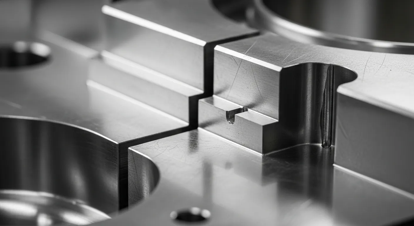
Parting lines in silicone molding are the points where mold halves meet, often resulting in "flash" or excess material. To minimize flash, place parting lines on the part’s sharpest edges or hidden surfaces. Precision-ground mold plates and vacuum-assisted venting are essential to keep flash thickness below our internal benchmark of 0.05mm.
At our facility, we utilize advanced CNC machining to create mold sets with high-tolerance shut-offs. This is particularly vital when choosing between silicone molding and rubber molding, as Liquid Silicone Rubber (LSR) flows into gaps as small as 0.005mm.
- Locate parting lines on non-cosmetic surfaces.
- Use "step" parting lines to provide a natural mechanical seal.
- Ensure gates are located away from critical sealing surfaces.
- Incorporate overflow grooves for compression molded parts to capture excess material.
Undercuts: The Silicone Superpower
Undercuts are features that prevent a part from being extracted from a straight-pull mold. In silicone molding, many undercuts can be "de-molded" by stretching the part over the mold core (bump-offs). This eliminates the need for expensive mechanical slides or lifters, provided the material elongation exceeds the undercut depth by a 3:1 safety margin.
We have successfully manufactured complex automotive seals and beauty device components where undercuts were essential for function. In our production runs, we’ve found that a "bump-off" is most successful when the silicone durometer is between 30A and 60A Shore.
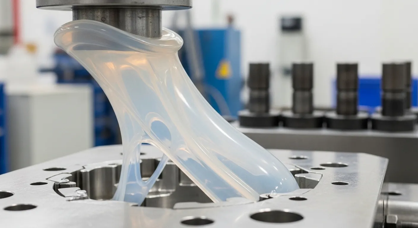
Tooling & Gate Selection for LSR vs. Compression
The selection between Liquid Silicone Rubber (LSR) injection and compression molding dictates gate placement. LSR requires precise gating—typically sub-gates or edge gates—to manage flow. Compression molding, conversely, uses a "pre-form" charge and no gate, making it ideal for large, simpler geometries or low-volume production where tooling cost is a primary concern.
As a one-stop OEM manufacturer, we provide a full DFM report within 2 working days to help you choose the right process. Our engineering team has found that for high-volume electronic components, LSR gating must be placed at the thickest section to prevent "jetting" and ensure a knit-line-free finish.
| Process Type | Gating Required | Surface Finish Quality | Best Use Case |
| LSR Injection | Yes (Pin/Sub) | Superior | High-volume, complex parts |
| Compression | No | Good | Large parts, low-cost tooling |
| Transfer | Yes (Pot/Gate) | Moderate | Medium complexity, inserts |
Frequently Asked Questions
Silicone typically shrinks between 2% and 4% during vulcanization. However, precision parts may experience "post-cure shrinkage" of an additional 1%. At SunOn, we calculate mold cavity dimensions using specific scaling factors based on the durometer and brand of silicone used.
Yes, silicone is excellent for overmolding. We specialize in bonding silicone to rigid substrates (like PA66 or Stainless Steel) using primers or self-bonding LSR grades. This process is commonly used in our medical and automotive projects to create integrated seals.
LSR is best for high-volume, high-precision parts requiring automated production and minimal manual labor. Compression molding is more cost-effective for larger parts, prototypes, or simpler designs with lower annual volumes. We provide a project risk evaluation to help determine the most economical path.
Yes. Every project at SunOn starts with a comprehensive DFM (Design for Manufacturing) report. Our engineers analyze your 2D/3D drawings to identify potential defects like air traps, sink marks, or difficult de-molding areas before the mold manufacture begins.