


Die Casting Mold Design: DFM, Gating, Cooling, and RFQ Guide
Die casting mold design converts a finished-part concept into a production tool capable of filling, cooling, ejecting, and repeating under high-pressure casting conditions.
It involves much more than creating a negative cavity of the component. The mold designer must coordinate the casting alloy, part geometry, die casting machine, parting line, runner and gate system, venting, overflows, thermal control, moving cores, ejection, tool steel, trimming, secondary machining, and expected production quantity.
For product engineers and technical buyers, the main question is not simply whether the mold can produce the required shape. It is whether the complete design can support stable filling, controlled solidification, practical maintenance, acceptable casting quality, and repeat production.
SunOn supports custom die casting mold projects from part DFM and mold-flow review through tool manufacturing, trial casting, optimization, and production support.
Die Casting Mold Design at a Glance
| Project Requirement | Main Mold Design Consideration |
|---|---|
| Visible cosmetic surface | Control gates, ejectors, vents, and parting lines |
| Thin or complex casting | Review filling path, gate velocity, and venting |
| Pressure-tight component | Manage porosity-sensitive zones and sealing surfaces |
| Side hole or undercut | Add a slide, core pull, insert, or secondary machining |
| High production quantity | Review cavity count, cooling, wear, and maintenance |
| Tight machined features | Add machining allowance and stable locating datums |
| High thermal load | Prioritize cooling layout, steel quality, and heat treatment |
| Large casting | Confirm machine capacity, locking force, and die support |
| Multiple related components | Compare separate, family, and multi-cavity tooling |
| Formal mold approval | Define trial stages, reports, tests, and acceptance criteria |
What Does Die Casting Mold Design Include?
A typical high-pressure die casting mold may include:
- Cover die and ejector die
- Core and cavity inserts
- Mold base and support plates
- Sprue, biscuit, or shot-entry interface
- Runner and gate system
- Overflows and vents
- Slides and movable cores
- Ejector pins and return mechanisms
- Cooling and heating channels
- Guide pillars and bushings
- Replaceable core pins and wear inserts
- Sensors and standard components
NADCA’s engineering training treats dimensional control, gating, thermal design, cooling, inserts, moving cores, ejection, shot control, and die spray as connected parts of die design rather than isolated decisions.
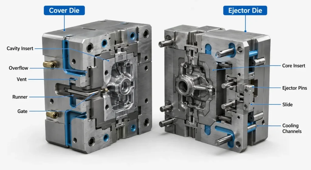
The mold should therefore be designed around the entire casting process—not only the CAD geometry of the final part.
Start With the Casting and Production Requirements
Before designing the mold, the engineering team should confirm:
- Casting alloy
- Part function
- Annual and lifetime quantities
- Target casting machine
- Required cavity count
- Cosmetic surfaces
- Critical dimensions and GD&T
- Pressure-tight or structural requirements
- Secondary CNC machining
- Surface finishing
- Testing and inspection
- Mold ownership and transfer plans
A mold designed without confirmed machine and production information may later require changes to its size, runner system, cooling, shot interface, slides, or ejection system.
Projects focused specifically on aluminum tooling can also reference SunOn’s aluminum die casting mold capabilities.
Review the Casting Geometry Before Designing the Mold
A mold cannot fully compensate for a casting geometry that is unsuitable for the selected process.
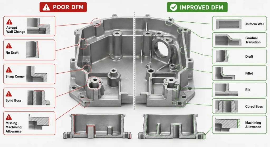
Maintain Controlled Wall Thickness
Walls should generally remain as consistent as practical. When thickness changes are functionally necessary, gradual transitions are preferable to abrupt steps.
NADCA Design notes that relatively uniform walls are preferred and that necessary variations should use transitions rather than sudden thickness changes.
Abrupt mass changes may affect:
- Filling
- Cooling
- Shrinkage
- Internal quality
- Surface appearance
- Dimensional stability
- Cycle consistency
Use Ribs Instead of Excessive Mass
Ribs can increase stiffness without creating unnecessarily thick solid sections. Their thickness, height, spacing, draft, and connection radius should be reviewed together.
NADCA Design identifies ribs as a way to add support while avoiding increased general wall thickness.
Design Bosses as Part of the Flow Path
Bosses may support screws, inserts, pivots, bearings, or assembly interfaces. Oversized solid bosses can create isolated heavy sections.
A central hole or cored structure can help control wall mass and may reduce secondary machining. NADCA’s boss guidance similarly recommends considering cored boss structures to maintain more uniform sections.
Add Draft, Fillets, and Machining Allowance
Draft supports mold release. Fillets improve flow transitions and reduce fragile mold edges. Machining allowance should be added only where later CNC operations are required.
The drawing should distinguish clearly between:
- As-cast dimensions
- Machined dimensions
- Final datums
- Machining stock
- Dimensions applying after finishing
Select the Parting Line and Die-Opening Direction
The parting line determines how the mold separates and which features are formed in the cover or ejector half.
Its position influences:
- Flash location
- Cosmetic appearance
- Ejection direction
- Casting retention
- Slide requirements
- Trimming
- Dimensional relationships
- Mold complexity
- Maintenance access
The casting should remain on the intended ejector side when the mold opens. Ejector pins must then remove it without excessive bending, twisting, marking, or damage.
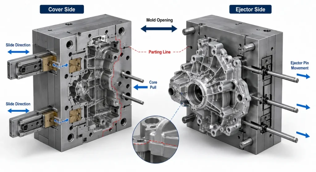
A poor parting-line decision can introduce unnecessary slides, visible flash, difficult trimming, weak mold details, or unstable dimensional relationships.
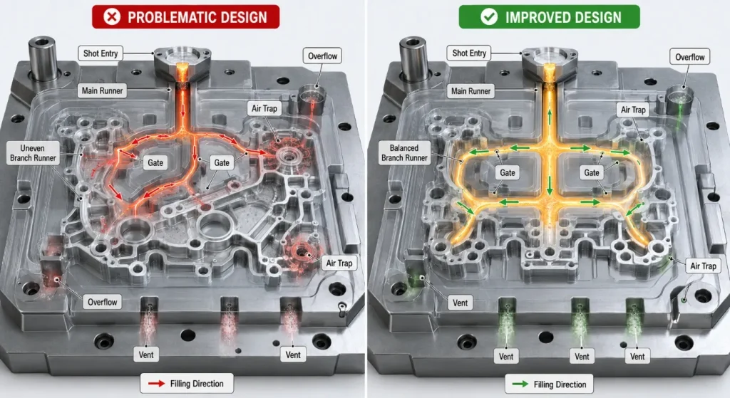
Design Gates, Runners, Overflows, and Vents as One System
The gating system controls how molten alloy enters and fills the cavity.
Its main elements may include:
- Shot entry
- Sprue or biscuit
- Main runner
- Branch runners
- Gates
- Overflows
- Vents
- Vacuum connections
Gate and runner design influences:
- Filling sequence
- Metal velocity
- Air entrapment
- Surface quality
- Local erosion
- Solidification
- Trimming
- Porosity-sensitive areas
Vents and overflows should be placed according to the expected filling pattern. They provide routes for displaced air, gases, cold metal, and final flow fronts.
Mold-flow simulation can support the evaluation of:
- Filling direction
- Gate location
- Air traps
- Weld or cold-shut risks
- Overflow positions
- Venting
- Solidification
- Local hot spots
Simulation supports engineering decisions but does not replace physical trials. SunOn’s cold-chamber die casting service connects DFM, flow analysis, tooling, trial casting, and process adjustment within one project route.
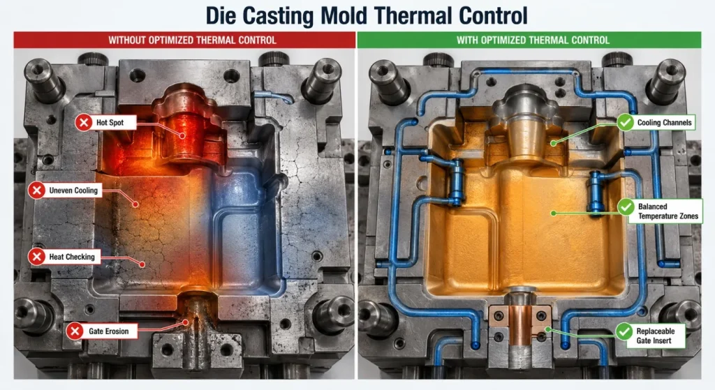
Build Thermal Control Into the Mold
A die casting mold is repeatedly heated by molten alloy and cooled through the mold body, cooling channels, die spray, and surrounding equipment.
The thermal-control design may include:
- Straight cooling lines
- Local cooling circuits
- Baffles
- Bubblers
- High-conductivity inserts
- Heating cartridges
- Separate circuits for slides or cores
- Flow and temperature monitoring
The objective is not simply to make the mold as cold as possible. The design should create a controllable and repeatable temperature distribution.
Poor thermal balance may contribute to:
- Premature solidification
- Local hot spots
- Distortion
- Dimensional drift
- Soldering
- Long or unstable cycles
- Uneven surface appearance
- Thermal fatigue
NADCA’s die-design curriculum includes multiple dedicated modules for thermal theory, thermal examples, and thermal control, reflecting the importance of cooling and temperature management in tool design.
Plan Slides, Cores, and Replaceable Inserts
Side holes, undercuts, reverse features, and complex internal geometry may require:
- Mechanical slides
- Hydraulic core pulls
- Angled core mechanisms
- Loose inserts
- Collapsible features
- Secondary CNC machining
Every moving mechanism adds:
- Mold components
- Fit and alignment requirements
- Wear surfaces
- Cycle-time effects
- Maintenance points
- Failure risks
- Sensor or confirmation requirements
Slides should be evaluated for locking, travel, support, lubrication, cooling, and collision avoidance.
Wear-sensitive details can be manufactured as replaceable inserts, including:
- Core pins
- Gate inserts
- Cavity details
- Slide wear plates
- Bushings
- Ejector pins
- Thread-forming components
Replaceable construction can reduce repair time and avoid remanufacturing a complete cavity block after localized wear or damage.
Select Tool Steel According to Service Conditions
Hot-work tool steels are commonly used for cavity inserts, cores, slides, and other components exposed to molten alloy, pressure, erosion, and thermal cycling.
The current ASTM A681 specification covers chemical, mechanical, and physical requirements for wrought alloy tool steels used in tools, dies, and fixtures. Material selection still depends on the mold design, service conditions, and required properties.
Tool-steel selection should consider:
- Casting alloy
- Melt temperature
- Insert size
- Thermal gradients
- Impact and mechanical load
- Erosion
- Soldering
- Crack resistance
- Polishing requirements
- Welding and repair
- Heat treatment
- Expected production volume
Premium hot-work steel can improve resistance to specific failure mechanisms, but steel grade alone does not determine mold life. Uddeholm’s die-casting guidance emphasizes that tool material, design, heat treatment, process conditions, and maintenance all contribute to tooling performance.
Control Ejection and Casting Removal
Ejection begins with the part geometry and shrinkage direction.
The design should evaluate:
- Which die half retains the casting
- Ejector-pin locations
- Pin size and quantity
- Casting stiffness
- Core shrinkage
- Surface-mark restrictions
- Slide return position
- Part-removal path
- Robot or operator access
Ejector pins should push against supported areas rather than thin cosmetic walls.
Air ejection, stripper plates, ejector sleeves, or specialized mechanisms may be considered when conventional pins are unsuitable.
Integrate Secondary Machining and Finishing
Many die castings require post-casting operations such as:
- CNC drilling
- Reaming
- Tapping
- Milling sealing surfaces
- Machining bearing bores
- Trimming
- Deburring
- Shot blasting
- Powder coating
- Plating
- Painting
- Assembly
The mold design should include stable machining locators and sufficient stock at machined features.
Gate remnants, ejector marks, flash, parting lines, and overflows should not interfere with later fixturing, sealing, coating, or assembly.
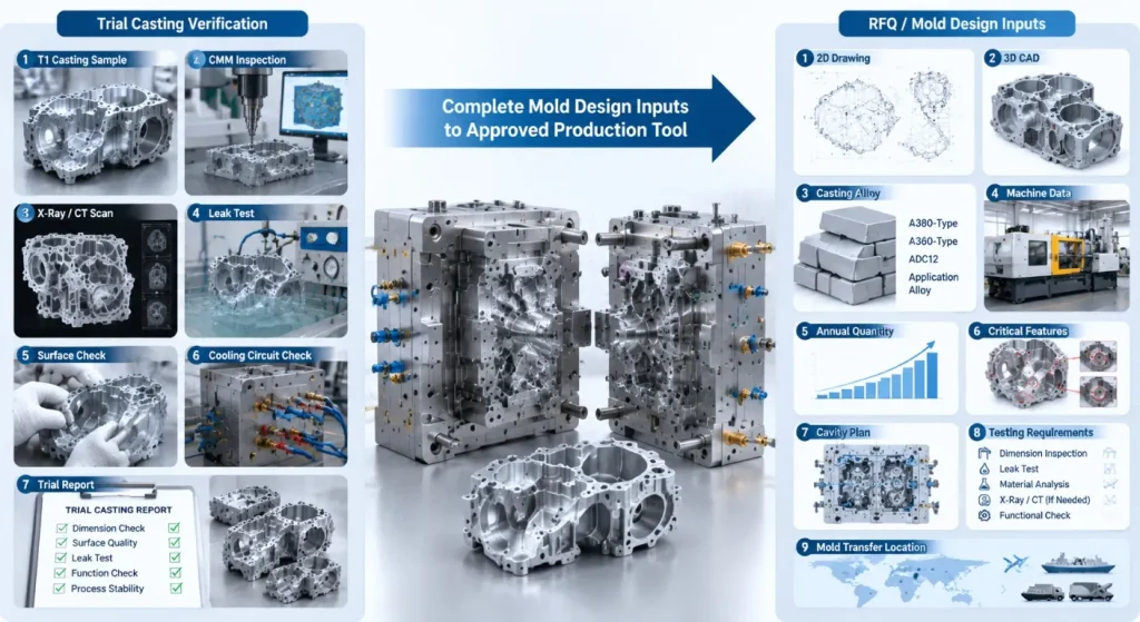
Validate the Design Through Trial Casting
A mold should not be approved only because it has been assembled successfully.
Trial casting should evaluate:
- Cavity filling
- Flash
- Ejection
- Surface quality
- Casting dimensions
- Porosity-sensitive regions
- Gate and overflow trimming
- Cycle stability
- Mold temperature
- Slide operation
- Cooling-circuit performance
- Secondary machining allowance
The approval plan may require:
- T1 samples
- Revised trial samples
- CMM reports
- X-ray or CT inspection
- Leak testing
- Machining trials
- Coating samples
- Production-rate validation
SunOn’s existing aluminum and zinc tooling workflow includes mold assembly, mold trials, tuning, and production stages.
From Part DFM to Approved Mold
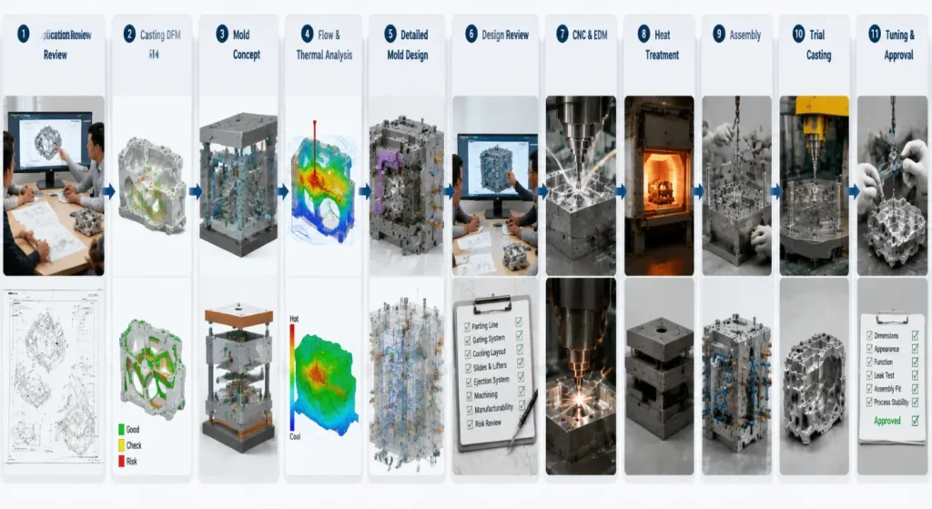
A controlled die casting mold design project generally follows:
- Application Review: Confirm alloy, machine, quantities, function, and quality requirements.
- Casting DFM: Review walls, draft, ribs, bosses, parting line, and machining allowance.
- Mold Concept: Define cavity count, die opening, slides, inserts, and ejection.
- Flow and Thermal Analysis: Evaluate gates, runners, vents, overflows, filling, and cooling.
- Detailed Mold Design: Complete inserts, mold base, cooling, slides, ejectors, and standard components.
- Design Review: Check dimensions, access, interference, strength, maintenance, and machine compatibility.
- Tool Manufacturing: Complete CNC machining, EDM, heat treatment, grinding, and polishing.
- Assembly and Bench Testing: Fit slides, ejectors, cooling circuits, sensors, and inserts.
- Trial Casting: Review filling, ejection, dimensions, appearance, and casting quality.
- Mold Tuning and Approval: Adjust the mold and process before production release.
Projects that are still validating geometry or demand may also compare production tooling with low-volume aluminum die casting.
What to Include in a Die Casting Mold Design RFQ
Provide:
- Controlled 2D part drawing
- 3D CAD model
- Casting alloy
- Part function
- Annual and lifetime quantities
- Target machine information
- Preferred cavity count
- Cosmetic surfaces
- Critical dimensions and GD&T
- Pressure-tight or structural requirements
- Secondary machining
- Surface treatment
- Insert and slide requirements
- Mold-steel expectations
- Trial and sample requirements
- Inspection and testing requirements
- Mold standard and preferred components
- Spare-parts requirements
- Mold-transfer location
- Production and delivery targets
A complete RFQ should define what the mold and finished casting must achieve—not only provide a 3D part model.
Frequently Asked Questions About Die Casting Mold Design
1. What Information Is Needed Before Die Casting Mold Design Begins?
The designer needs the 2D drawing, 3D model, alloy, machine information, quantities, critical dimensions, cosmetic zones, machining, testing, and delivery requirements. Missing production information can lead to later changes in the mold base, runner, cooling, slides, or cavity count.
2. How Is the Parting Line Selected?
The parting line is selected according to die opening, casting retention, ejection, flash, cosmetic surfaces, trimming, undercuts, and dimensional relationships. The simplest visual location is not always the most stable manufacturing choice.
3. Does Mold-Flow Simulation Eliminate the Need for Trial Casting?
No. Simulation can help predict filling, air entrapment, solidification, and hot spots, but it depends on input data and modeling assumptions. Trial casting is still required to confirm actual mold and process behavior.
4. How Many Cavities Should a Die Casting Mold Have?
Cavity count depends on part size, machine capacity, annual quantity, filling balance, thermal control, quality risk, and tooling investment. More cavities do not automatically produce a lower total project cost.
5. Which Tool Steel Is Best for a Die Casting Mold?
H13-type hot-work steel is a common starting point, while premium grades may be considered for more demanding thermal or mechanical conditions. The final decision should include heat treatment, insert size, casting alloy, expected wear, repair strategy, and production volume.
6. What Should Be Checked During Mold Trials?
Trials should evaluate filling, flash, ejection, dimensions, surface condition, porosity-sensitive areas, trimming, cooling, slides, cycle stability, and secondary machining. Required reports and tests should be agreed before tooling manufacture.
Conclusion
Reliable die casting mold design integrates casting geometry, metal flow, thermal control, parting, ejection, moving cores, tool steel, secondary machining, trials, and maintenance.
The best design is not necessarily the mold with the most slides, highest cavity count, hardest steel, or largest number of cooling channels. It is the design that supports stable casting quality, practical maintenance, controlled production, and the required lifetime economics.
To request a mold-design review, contact SunOn with your part files, alloy, quantities, machine information, critical requirements, trial plan, and mold-delivery expectations.
