


Die Casting Mold: Design, Tool Steel, DFM, and RFQ GuideSEO Title
A die casting mold is a precision production tool used to form aluminum, zinc, magnesium, and other suitable alloys under pressure. It defines the external geometry, internal features, parting line, gate location, ejector marks, dimensional relationships, and many surface characteristics of the finished casting.
However, a die casting mold should not be evaluated only by cavity dimensions or quoted tooling life. Casting alloy, wall thickness, metal flow, thermal balance, venting, ejection, trimming, secondary machining, production quantity, and maintenance all influence mold performance.
For product engineers and technical buyers, the practical question is not simply whether a supplier can manufacture the mold. It is whether the mold can fill, cool, eject, repeat, and remain serviceable under the intended production conditions.
SunOn supports custom die casting mold projects from drawing review and mold engineering through trial casting, process adjustment, and production support.
Die Casting Mold at a Glance
| Project Requirement | Typical Engineering Direction |
|---|---|
| Prototype or changing design | Review simplified or bridge tooling |
| Stable repeat production | Consider dedicated production tooling |
| Higher required output | Review multi-cavity design and machine capacity |
| Side holes or undercuts | Use slides, core pulls, or replaceable inserts |
| Cosmetic exterior | Control gate, vent, ejector, and parting-line locations |
| Pressure-tight component | Review metal flow, porosity risk, sealing areas, and testing |
| High thermal load | Prioritize tool steel, heat treatment, cooling, and preheating |
| Wear-sensitive details | Use replaceable cores, pins, and cavity inserts |
| Secondary CNC machining | Add machining allowance and stable locating features |
| Formal mold approval | Define trial stages, sample reports, and acceptance criteria |
What Is a Die Casting Mold?
A die casting mold—also called a die casting die or die casting tool—is a hardened metal tool installed in a die casting machine.
Molten alloy is delivered into the mold cavity under controlled pressure. The alloy fills the cavity, solidifies, and is then ejected as a near-net-shape casting.
A typical mold may contain:
- Cover die and ejector die
- Core and cavity inserts
- Mold base and support plates
- Runner and gate system
- Overflow and venting areas
- Slides and movable cores
- Ejector pins and return components
- Cooling or heating channels
- Replaceable core pins
- Guide pillars and bushings
- Sensors and standard components
The mold should be designed as part of a complete casting system. Part geometry, alloy, machine, shot system, trimming method, inspection, and expected production volume must be considered together.
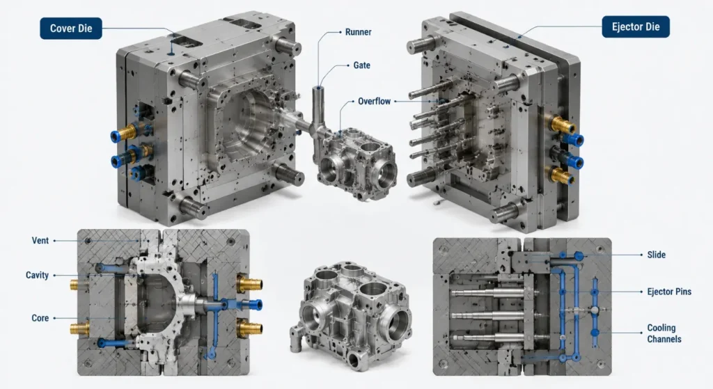
Projects focused specifically on aluminum tooling can also reference SunOn’s aluminum die casting mold capabilities.
Start With the Casting Design
A good mold cannot fully correct a casting design that is unsuitable for pressure die casting.
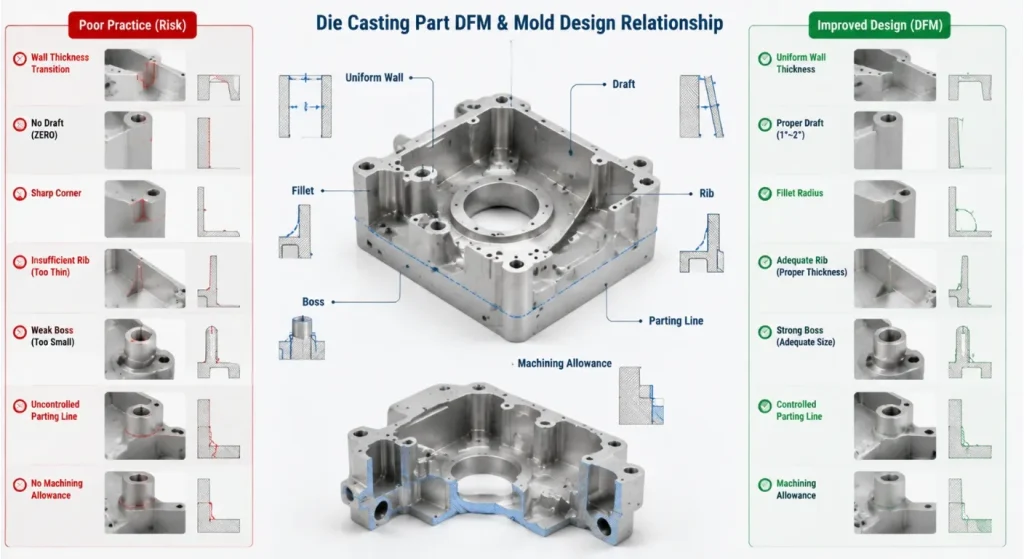
The NADCA design guidance highlights several recurring design considerations.
Wall Thickness
Large and abrupt thickness changes can create uneven filling, cooling, shrinkage, and internal-quality risks.
Designers should aim for:
- Relatively consistent wall sections
- Gradual transitions
- Ribs instead of unnecessarily thick solid areas
- Local reinforcement only where function requires it
The appropriate wall thickness depends on alloy, part size, flow length, machine capacity, structural requirements, and casting conditions.
Draft
Surfaces parallel to the mold-opening direction generally require draft so the casting can release without excessive force or surface damage.
The required draft varies with:
- Alloy
- Surface depth
- Internal or external geometry
- Surface texture
- Ejection method
- Dimensional requirement
NADCA’s die casting draft guidance explains that draft is not a single fixed angle for every surface.
Fillets and Radii
Sharp transitions can interfere with metal flow and increase localized stress in both the casting and mold.
Suitable fillets can:
- Improve filling
- Reduce stress concentration
- Support smoother ejection
- Improve tool manufacturability
- Reduce fragile mold edges
Ribs and Bosses
Ribs can improve stiffness without creating excessively thick sections. Bosses may support screws, inserts, mounting points, or assembly features.
Their design should consider:
- Wall connection
- Fillet radius
- metal flow
- Core strength
- Ejection
- Secondary machining
- Local porosity risk
Parting Line, Ejection, and Moving Features
The parting line determines how the mold opens and which features remain in the cover or ejector side.
Its location can influence:
- Flash
- Cosmetic appearance
- Dimensional relationships
- Trimming
- Slider requirements
- Ejection direction
- Mold complexity
The casting should preferably remain on the intended ejector side when the mold opens.
Ejector pins should push the casting out without excessive bending, twisting, marking, or local deformation. Pin size, quantity, location, support, and casting stiffness must be reviewed together.
Undercuts and side features may require:
- Slides
- Angled lifters
- Hydraulic core pulls
- Mechanical core pulls
- Loose inserts
- Secondary CNC machining
Each moving feature adds components, fitting requirements, maintenance points, and potential wear.
Single-Cavity, Multi-Cavity, and Family Molds
Single-Cavity Mold
A single-cavity mold produces one casting per cycle.
It may suit:
- Larger components
- Lower initial demand
- Complex slide structures
- Development projects
- Parts requiring significant thermal control
Multi-Cavity Mold
A multi-cavity mold produces several identical castings per cycle.
It may improve output, but the design must maintain balanced:
- Metal flow
- Cavity filling
- Cooling
- Ejection
- Venting
- Dimensional behavior
Increasing cavity count without considering machine shot capacity and thermal balance can reduce process stability.
Family Mold
A family mold produces different components in the same cycle.
It may reduce tooling investment for related parts, but different component volumes and flow paths can make filling and thermal balance more difficult. Family tooling should be selected only after evaluating production ratio, part geometry, quality risk, and replacement demand.
Choosing Tool Steel and Mold Components
Hot-work tool steel is commonly used for cavity inserts, cores, slides, and other components exposed to molten alloy, pressure, wear, and thermal cycling.
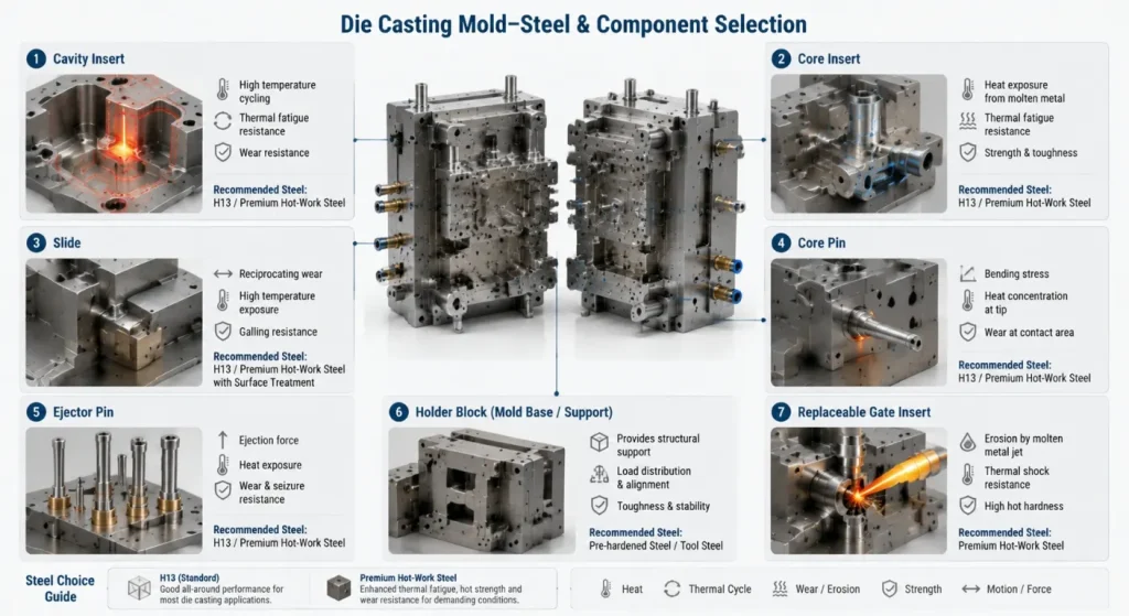
ASTM A681 covers chemical, mechanical, and physical requirements for wrought alloy tool steels used in tools, dies, and fixtures.
H13 Tool Steel
H13 is widely associated with hot-work and die casting applications because it combines hot strength, toughness, wear resistance, and resistance to thermal fatigue.
The FINKL H13 technical data identifies H13 as suitable for high-temperature tooling applications requiring impact and wear resistance.
The complete specification should still define:
- Steel producer or quality level where required
- Remelting requirement
- Heat treatment
- Target hardness
- Stress relief
- Surface treatment
- Inspection and certification
Premium Hot-Work Steels
For large dies, severe thermal cycles, high mechanical loading, or demanding production targets, a premium hot-work grade may be evaluated.
Uddeholm Dievar is one example developed for applications requiring toughness and resistance to heat checking.
Premium steel does not automatically guarantee long mold life. Die design, heat treatment, cooling, preheating, process control, maintenance, and repair methods remain important.
Replaceable Components
Wear-sensitive or damage-prone areas may use replaceable:
- Core pins
- Cavity inserts
- Gate inserts
- Ejector pins
- Slide wear plates
- Bushings
- Date inserts
- Thread-forming inserts
Replaceable components can simplify repair and reduce the need to remake a complete cavity block.
Metal Flow, Gating, Venting, and Thermal Control
The runner and gate system delivers molten metal into the cavity.
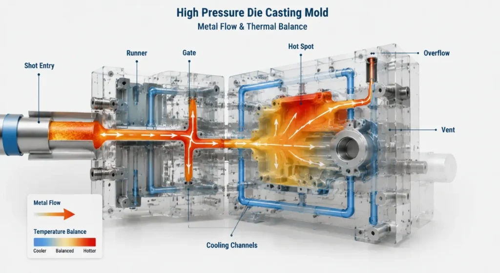
Its design influences:
- Filling sequence
- Flow velocity
- Air entrapment
- Surface quality
- Solidification
- Trimming
- Local erosion
- Porosity risk
Vents and overflows provide routes for displaced air, gases, cold metal, and initial flow fronts. They must be positioned according to the expected filling pattern rather than added only after defects appear.
Cooling channels and local thermal-control features remove heat and help maintain a repeatable mold-temperature distribution.
Poor thermal balance may contribute to:
- Long or unstable cycles
- Local hot spots
- Premature solidification
- Distortion
- Soldering
- Dimensional variation
- Heat checking
Mold-flow and thermal simulation can support gate, runner, vent, overflow, and cooling decisions. Simulation should guide engineering and trials rather than replace physical validation.
SunOn’s cold-chamber die casting service describes how DFM, flow analysis, tool engineering, and trial adjustments are connected in a die casting project.
From DFM to Trial Casting
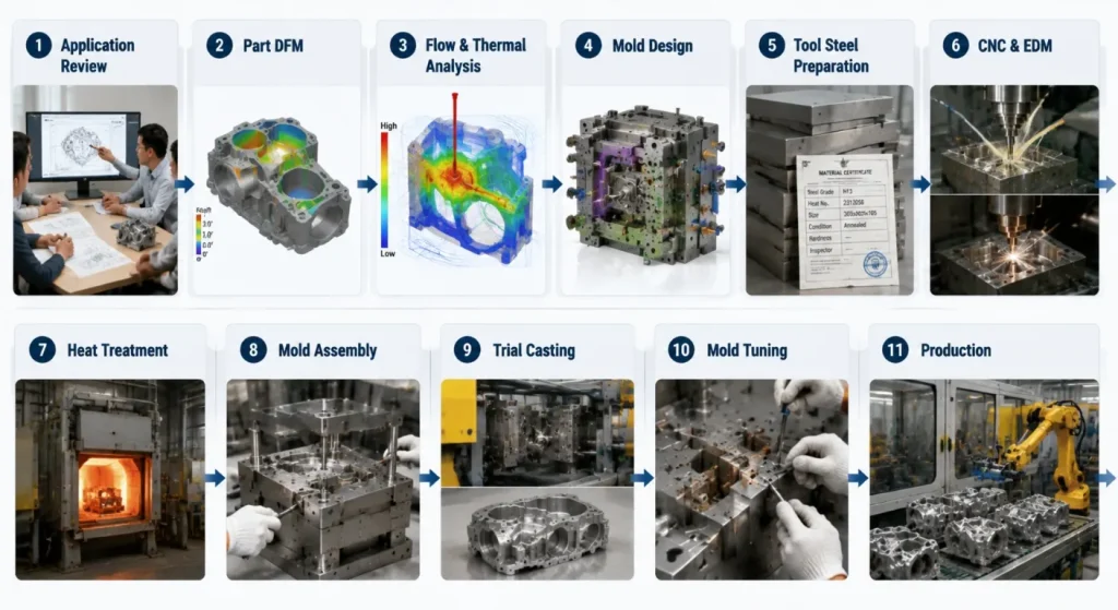
A controlled die casting mold project commonly follows these stages:
- Application Review: Confirm part function, alloy, machine, quantity, and quality requirements.
- Part DFM: Review wall thickness, draft, ribs, bosses, undercuts, machining allowance, and ejectability.
- Flow and Thermal Review: Evaluate gate, runner, venting, overflow, filling, and cooling concepts.
- Mold Design: Complete parting line, inserts, slides, ejection, cooling, and mold-base design.
- Steel Verification: Confirm tool steel, certificates, stock condition, and heat-treatment plan.
- CNC and EDM Manufacturing: Machine cavity blocks, cores, slides, plates, and detailed features.
- Heat Treatment and Finishing: Complete hardening, tempering, stress relief, grinding, polishing, and surface treatment.
- Mold Assembly: Fit inserts, sliders, ejector systems, cooling circuits, and standard components.
- Trial Casting: Evaluate filling, ejection, surface condition, dimensions, trimming, and casting defects.
- Mold Tuning: Adjust process conditions or tooling features based on trial results.
- Approval and Production: Confirm samples, documents, process window, maintenance, and production readiness.
For projects still validating casting geometry or demand, low-volume aluminum die casting may support process evaluation before a full production strategy is finalized.
Mold Trial and Acceptance
A mold should be approved according to defined casting and tooling requirements, not only because it opens and closes correctly.
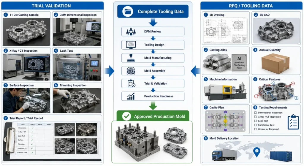
Trial review may include:
- Complete cavity filling
- Surface appearance
- Flash and trimming
- Ejection marks
- Casting dimensions
- Porosity-sensitive regions
- Leak or pressure testing
- Secondary machining allowance
- Cycle stability
- Mold temperature distribution
- Slide and ejector operation
- Cooling-circuit performance
The buyer should define whether approval requires:
- Initial trial samples
- Revised samples
- Dimensional reports
- Material verification
- X-ray or CT inspection
- Leak testing
- Machining trials
- Surface-finish evaluation
- Production-rate demonstration
The acceptance plan should be included in the quotation because trial quantities, testing, reports, shipping, and tuning affect project cost and timing.
Mold Maintenance and Common Failure Risks
Die casting mold life should not be reduced to one guaranteed number of shots.
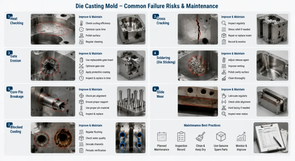
Service life depends on:
- Casting alloy and temperature
- Tool steel and quality
- Mold size and geometry
- Heat treatment
- Thermal cycling
- Cooling efficiency
- Preheating
- Gate velocity
- Lubrication
- Cleaning
- Maintenance
- Repair history
Common risks include:
- Heat checking
- Gross cracking
- Gate erosion
- Soldering
- Washout
- Core-pin breakage
- Ejector wear
- Slide wear
- Cooling-channel blockage
- Dimensional drift
Preventive maintenance may include cleaning, inspection, lubrication, cooling-circuit checks, insert replacement, crack monitoring, surface repair, and dimensional verification.
Tool-life responsibility should also be defined when the mold is transferred between the tooling supplier and a separate casting plant.
What to Include in a Die Casting Mold RFQ
Provide:
- Controlled 2D part drawing
- 3D CAD model
- Casting alloy and specification
- Part function and application
- Annual and lifetime quantities
- Target machine type or available machine information
- Cavity preference
- Cosmetic surfaces
- Critical dimensions and GD&T
- Pressure-tight or structural requirements
- Secondary machining allowance
- Surface finish and coating
- Insert and slider requirements
- Expected mold steel and life strategy
- Trial and sample requirements
- Inspection and testing requirements
- Mold standard and preferred components
- Mold-transfer requirements
- Spare parts and maintenance requirements
- Production location and delivery target
SunOn’s aluminum and zinc alloy die casting mold page provides additional context for tooling, trial casting, mold tuning, and production support.
Frequently Asked Questions
1. What Is the Difference Between a Die Casting Mold and a Die Casting Die?
The terms are commonly used interchangeably. “Die” is more traditional in metal casting, while many international buyers and manufacturers also use “mold” or “tooling.”
2. Which Tool Steel Is Best for a Die Casting Mold?
H13 is a common starting point for many hot-work die components, but it is not automatically correct for every project. Alloy temperature, insert size, thermal cycling, wear, cracking risk, heat treatment, and production target should guide the final grade.
3. How Long Does a Die Casting Mold Last?
There is no universal mold-life figure. Service life depends on alloy, die steel, heat treatment, mold design, thermal balance, process settings, maintenance, repair history, and casting geometry.
4. Can the Same Mold Be Used for Aluminum and Zinc Die Casting?
It is generally not advisable to assume direct interchangeability. Aluminum and zinc projects can require different machine systems, thermal conditions, shrinkage allowances, gates, cooling, materials, and process settings.
5. What Is the Difference Between a Prototype Mold and a Production Mold?
Prototype or bridge tooling prioritizes design validation, lower initial investment, and easier modification. Production tooling prioritizes cycle stability, maintenance access, repeatability, cavity strategy, and the intended lifetime volume.
6. What Information Is Needed for a Die Casting Mold Quote?
Provide 2D and 3D part files, alloy, quantities, machine information, critical dimensions, cosmetic requirements, testing, cavity preference, tool steel expectations, trial requirements, and mold-delivery location. Secondary machining and pressure-tight requirements should also be defined.
Conclusion
A reliable die casting mold begins with a castable part design and a clearly defined production target.
Parting line, draft, wall thickness, metal flow, venting, cooling, ejection, tool steel, cavity strategy, secondary machining, and maintenance should be evaluated as one system.
The best mold is not necessarily the mold with the highest cavity count, hardest steel, or most complex cooling circuit. It is the mold that supports repeatable casting quality, practical maintenance, stable production, and the required lifetime economics.
To request a tooling review, contact SunOn with your part drawings, casting alloy, quantities, machine information, critical requirements, trial plan, and mold-delivery expectations.
