


Fixture CNC Machining: Design, Materials, Tolerances, and RFQ Guide
Fixture CNC machining is used to manufacture custom workholding, assembly, inspection, welding, and test fixtures that locate components in a controlled position during production.
A fixture is not only a machined plate with several holes. Its performance depends on how the workpiece is located, supported, clamped, loaded, released, cleaned, inspected, and maintained.
For manufacturing engineers and technical buyers, the practical question is not simply whether a supplier can machine the fixture. It is whether the complete fixture can locate the workpiece repeatably, resist process forces, provide tool and operator access, and remain serviceable over its intended production life.
SunOn can review drawing-based fixture components through its custom CNC machining services and broader industrial CNC machining support.
Fixture CNC Machining at a Glance
| Fixture Requirement | Typical Direction |
|---|---|
| Prototype or design-validation fixture | CNC-machined aluminum may support faster modification |
| Repeated machining loads | Review steel, tool steel, or hardened wear components |
| Corrosive or washdown environment | Consider stainless steel and protected components |
| Inspection or metrology fixture | Prioritize stable datums and low-distortion clamping |
| Multiple product variants | Review modular or adjustable fixture architecture |
| Complex access on several faces | Consider multi-axis machining |
| High-wear locating points | Use replaceable pins, bushings, pads, or inserts |
| Operator-loaded production | Add loading clearance and mistake-proofing |
| Automated loading | Define robot access, sensors, and part presentation |
| Formal acceptance | Specify fixture verification and trial requirements |
What Is Fixture CNC Machining?
Fixture CNC machining produces custom workholding and production aids from metal or engineering-plastic stock using milling, turning, drilling, boring, reaming, threading, grinding, and related processes.
Carr Lane distinguishes fixtures from jigs by explaining that fixtures support and locate a workpiece, while jigs also guide the cutting tool. In modern CNC production, many custom workholders are fixtures because the CNC machine controls the tool path.
Common categories include:
- Machining fixtures
- Assembly fixtures
- Inspection fixtures
- Welding fixtures
- Functional test fixtures
- Trimming and secondary-operation fixtures
- Robot-loading nests
- Automation pallets
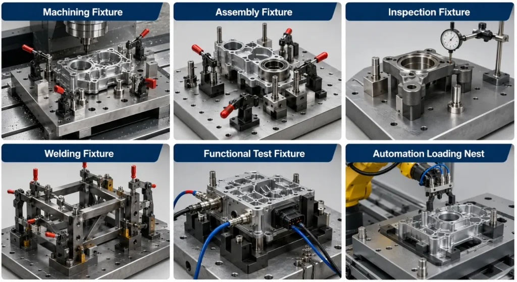
The fixture design should begin with the workpiece, manufacturing operation, loading method, and required output—not with an existing fixture plate or clamp arrangement.
Start With Locating, Then Add Clamping
The first function of a fixture is to locate the workpiece. The second is to hold it against the locators while resisting machining, assembly, inspection, or welding forces.
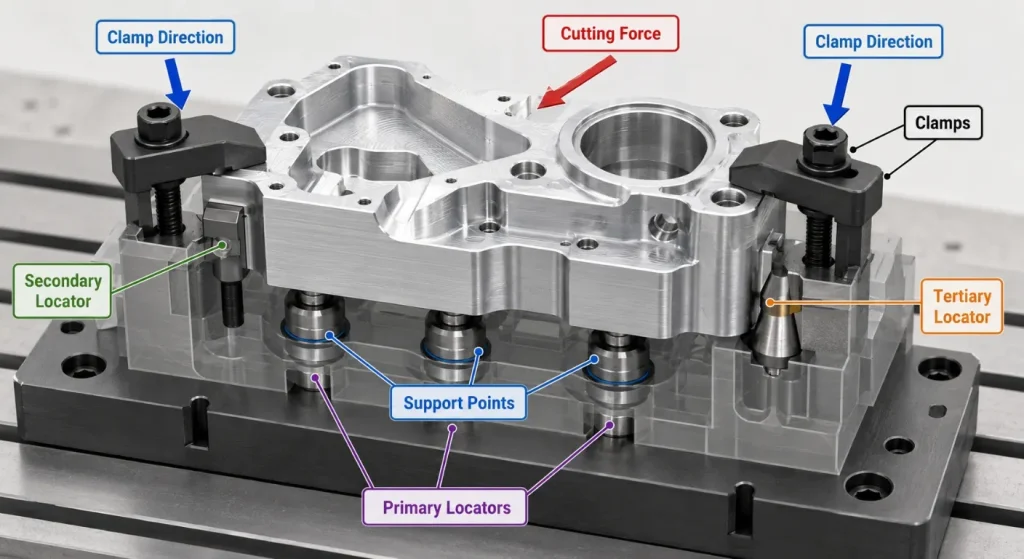
Carr Lane’s locating and clamping principles emphasize that clamps should not determine the part position. They should hold the workpiece against the established locating points.
A practical locating plan should consider:
- Functional datum surfaces
- Workpiece degrees of movement
- Locator spacing and stability
- Raw-material or molded-part variation
- Full-seating confirmation
- Cleaning and maintenance access
- Replaceable wear points
Clamping should then be reviewed for force direction, workpiece stiffness, process loads, accessibility, safety, loading time, and interference with tools or gauges.
More clamping force is not automatically better. Excessive force can distort thin parts, mark cosmetic surfaces, or move the component away from its intended datums.
Common Fixture Types and Applications
Machining Fixtures
Machining fixtures hold workpieces during milling, turning, drilling, grinding, or secondary processing.
They may incorporate:
- Fixture plates
- Locating pins
- Rest pads
- V-blocks
- Clamps
- Soft jaws
- Rotary bases
- Vacuum channels
- Hydraulic or pneumatic clamping
Tool access, chip evacuation, coolant flow, spindle clearance, and probe access should be reviewed before fixture production.
Assembly Fixtures
Assembly fixtures support repeatable alignment during fastening, press fitting, adhesive bonding, component insertion, connector installation, and subassembly verification.
They should reduce operator variation without making loading, fastening, or part removal unnecessarily difficult.
Inspection Fixtures
Inspection fixtures establish repeatable references for gauges, optical measurement, coordinate measuring machines, or functional checks.
They should hold the component without changing the characteristic being measured. Thin metal parts, flexible plastic parts, seals, and cosmetic surfaces may require low-force support.
Welding Fixtures
Welding fixtures locate components before and during welding. Their design should consider torch access, grounding, spatter, heat, shrinkage, clamping sequence, and post-weld removal.
A rigid fixture cannot automatically prevent all welding distortion. Joint design, welding sequence, heat input, material, and release strategy still affect the result.
Choosing Materials for CNC-Machined Fixtures
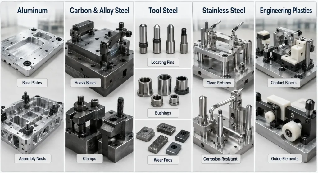
Aluminum
Aluminum is commonly considered for prototype fixtures, inspection nests, assembly tools, lightweight pallets, and fixtures requiring frequent manual handling.
Contact surfaces may wear under repeated loading, so replaceable steel pins, bushings, pads, or inserts may be added.
Carbon and Alloy Steel
Steel may suit machining fixtures, heavy-duty bases, clamps, supports, and components exposed to repeated loads or impact.
The drawing should specify the grade, heat treatment, hardness, corrosion protection, and grinding requirements rather than stating only “steel.”
Tool Steel
Tool steel may be used selectively for:
- High-wear locators
- Drill bushings
- Hardened pads
- Punches
- Guide components
- Replaceable nests
Using hardened material only at wear points may be more practical than manufacturing the complete fixture from tool steel.
Stainless Steel
Stainless steel can be considered for washdown, food-processing, laboratory, medical-equipment-related, or corrosion-exposed fixtures.
The exact grade should reflect corrosion exposure, strength, cleaning, welding, and machining requirements.
Engineering Plastics
Engineering plastics can be used for non-marring contacts, low-friction guides, insulating supports, lightweight nests, and replaceable workpiece-contact surfaces.
Creep, moisture absorption, operating temperature, wear, and clamping deformation should be reviewed before material approval.
Match the CNC Process to Fixture Geometry
CNC milling is the principal process for:
- Fixture plates
- Workpiece nests
- Pockets
- Slots
- Mounting patterns
- Datum surfaces
- Clamp brackets
- Sensor mounts
CNC turning suits locating pins, bushings, rollers, sleeves, spacers, and round clamp components.
Five-axis CNC machining may support complex nests, angled access, multi-face datum relationships, or contoured workpiece supports. Its value lies in reducing repositioning and maintaining relationships between features, not simply in using a more complex machine.
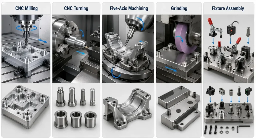
Grinding may be required for hardened locators, precision pads, reference surfaces, or bushings after heat treatment.
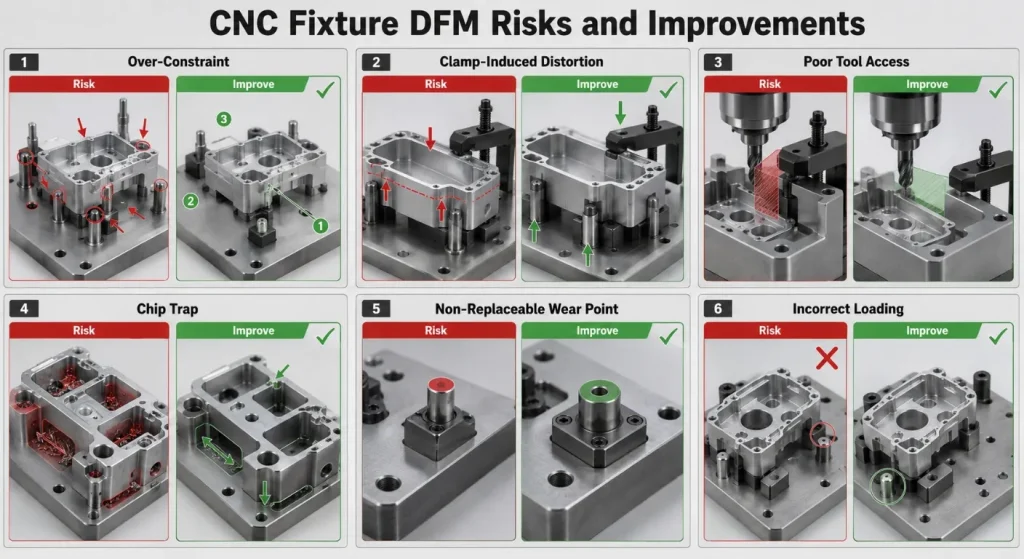
Key DFM Risks in Fixture CNC Machining
Over-Constraint
Too many rigid locating points can prevent consistent seating when the workpiece has normal dimensional variation.
The fixture should constrain the necessary movement without creating conflicting contact points.
Clamp-Induced Distortion
Clamps positioned far from supports can bend the workpiece. Clamping closer to supported areas and directing force toward locators can reduce this risk.
Poor Tool and Probe Access
Clamps, walls, bolts, and fixture components can block cutting tools, toolholders, chips, inspection probes, or removal paths.
Access should be reviewed using the actual spindle envelope, toolholder dimensions, probes, robot grippers, and operator-loading method.
Chip and Coolant Traps
Flat pockets and enclosed corners can collect chips. A chip trapped under a datum pad can change the workpiece position and create batch variation.
Drainage, relief areas, cleanout access, air-blast paths, and sloped surfaces may be required.
Non-Replaceable Wear Surfaces
Locating pins, support pads, threads, clamp contacts, and nests can wear during repeated production.
Replaceable components simplify maintenance and reduce the need to remachine the complete fixture.
Incomplete Mistake-Proofing
A workpiece that can be loaded backward, upside down, or into the wrong station can cause scrap or equipment damage.
Asymmetric locators, keys, sensors, mechanical stops, and clear loading access can support error prevention.
Modular, Dedicated, and Prototype Fixtures
A prototype fixture is useful when the workpiece design or production process is still changing. It should allow adjustment and learning rather than lock the process too early.
A modular fixture uses reusable plates, grids, pins, clamps, and standard mounting components. It may reduce initial engineering effort for low-volume or changing products.
A dedicated fixture is designed for one part or product family. It can improve loading speed, access, repeatability, and automation readiness when production demand justifies the additional design and machining effort.
The correct approach depends on:
- Product maturity
- Order quantity
- Design-change frequency
- Required cycle time
- Manual or automated loading
- Process forces
- Maintenance plan
- Future product variants
For engineering samples and initial production tools, low-volume CNC machining can support fixture validation before a dedicated long-term design is finalized.
Fixture Verification and Process Validation
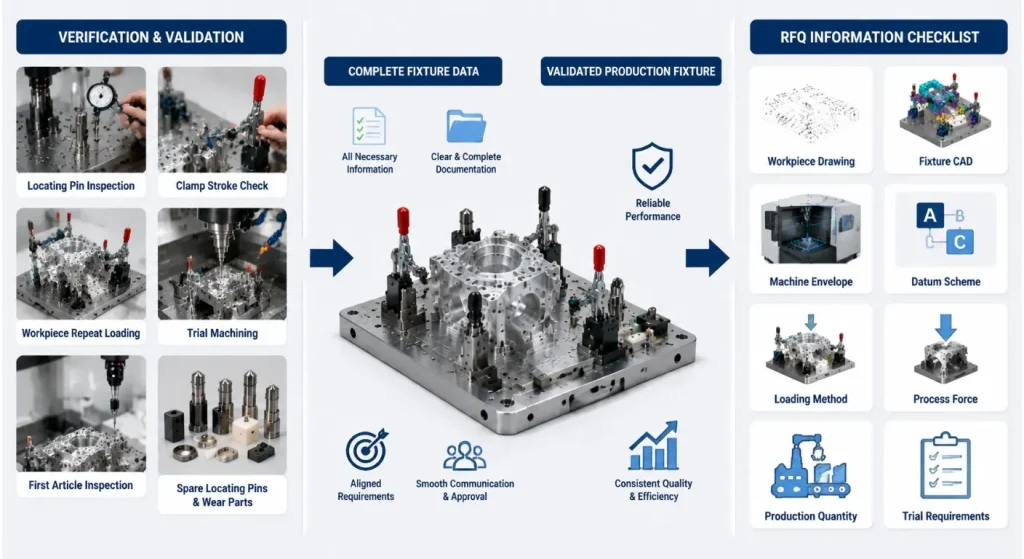
A finished fixture should be verified as an assembly, not only as a collection of individual machined components.
Verification may include:
- Datum and locator inspection
- Clamp travel and force review
- Repeat loading tests
- Trial machining or assembly
- Part-removal evaluation
- Gauge or probe access
- Chip and coolant review
- First-part inspection
- Repeatability studies where required
Renishaw explains that machine-tool probes can support automated workpiece setup and in-process inspection.
Probing may help confirm fixture position, pallet location, or workpiece seating, but it does not replace a sound mechanical locating and clamping strategy.
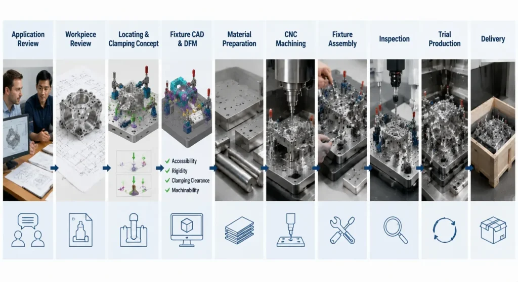
From Application Review to Fixture Delivery
A controlled fixture CNC machining project commonly follows these stages:
- Application Review: Confirm the fixture function and production operation.
- Workpiece Review: Evaluate drawings, CAD models, variation, and contact surfaces.
- Datum and Clamping Concept: Define locating, support, and force directions.
- Fixture CAD and DFM: Review access, rigidity, maintenance, and standard components.
- Material Confirmation: Select base materials, wear inserts, finishes, and purchased parts.
- CNC Machining: Produce plates, nests, pins, brackets, and fixture components.
- Assembly and Adjustment: Install clamps, pins, sensors, bushings, and accessories.
- Inspection: Verify datum surfaces, locations, movement, and assembled relationships.
- Trial Production: Confirm loading, access, repeatability, and first-part results.
- Documentation and Delivery: Supply agreed records, spare components, and packaging.
What to Include in a Fixture CNC Machining RFQ
Provide:
- Workpiece 2D drawing and 3D CAD model
- Fixture drawing or initial concept, if available
- Operation performed in the fixture
- Machine type and working envelope
- Cutting, assembly, welding, or test loads
- Functional datum system
- Required locating repeatability
- Expected workpiece variation
- Manual, pneumatic, hydraulic, vacuum, or robotic loading
- Required clamps, sensors, pins, bushings, and standard components
- Fixture material and surface treatment
- Expected production quantity and cycle
- Wear and maintenance requirements
- Inspection and trial requirements
- Packaging and delivery destination
SunOn’s CNC machining quotation guide provides additional guidance for preparing drawings, quantities, tolerances, secondary processes, and inspection notes.
A complete RFQ should explain what the fixture must achieve—not only provide a fixture plate drawing.
Frequently Asked Questions About Fixture CNC Machining
1. What Is the Difference Between a Jig and a Fixture?
A fixture locates and holds the workpiece, while a jig also guides a cutting tool. In CNC machining, custom workholders are commonly described as fixtures because the machine controls the tool path.
2. Which Material Is Best for a CNC-Machined Fixture?
Aluminum suits many prototypes, inspection nests, and lightweight tools, while steel or tool steel may suit repeated loads and high-wear locations. Stainless steel or engineering plastics may be selected for corrosion resistance, cleaning, insulation, or non-marring contact.
3. How Accurate Does a Machining Fixture Need to Be?
Fixture accuracy should be based on the workpiece tolerance, datum strategy, process capability, and required locating repeatability. Not every fixture dimension requires a tight tolerance; priority should be given to locators, datum surfaces, clamp relationships, and machine interfaces.
4. Can One Fixture Hold Several Product Variants?
Yes, modular locators, adjustable stops, replaceable nests, and interchangeable plates can support related variants. The design should prevent incorrect combinations and maintain the required datum relationship for each version.
5. How Is a CNC Fixture Verified Before Production?
Verification may include dimensional inspection, repeated loading, clamp checks, trial machining, first-part inspection, probe-access review, and repeatability studies. The required acceptance process should be agreed before fixture manufacturing begins.
6. What Information Is Needed for a Fixture Machining Quote?
Provide the workpiece drawing and CAD model, fixture function, machine envelope, datum requirements, loading method, production quantity, standard components, materials, process forces, inspection, and trial requirements. A fixture concept or existing design should also be included when available.
Conclusion
Fixture CNC machining should begin with the workpiece, production process, and functional datums.
A successful fixture must locate the component repeatably, hold it without harmful distortion, resist process forces, maintain tool and operator access, manage chips or contamination, and remain serviceable over its intended production life.
Material, clamping, modularity, wear components, inspection, automation access, and expected quantity should be evaluated together.
To request a fixture manufacturability review, contact SunOn with the workpiece files, fixture concept, operation, machine information, loading method, repeatability requirement, standard components, and trial expectations.
