


Plastic Injection Molds for Cooling Components | Custom Tooling by SunOn
SunOn designs and manufactures each plastic injection mold for cooling components around the customer’s actual part geometry, resin, assembly requirements, critical dimensions, and production volume. Our service covers the full tooling workflow, from CAD review and DFM to mold fabrication, T1 sampling, adjustment, and optional molded-part production.
This service is intended for plastic parts used in cooling and thermal-management assemblies. It does not refer to replacement cooling channels, baffles, fittings, or other accessories installed inside an existing injection mold.
Upload your 2D drawings and 3D CAD files for a DFM review and custom tooling quote.
Custom Injection-Mold Tooling for Cooling-System Components
Cooling-system plastic parts can include thin walls, structural ribs, mounting points, mating surfaces, complex flow paths, or features that must align accurately with surrounding components. These requirements must be considered before mold steel is cut.
SunOn reviews the complete part design and intended production conditions before developing the tooling structure. The mold is planned according to the selected resin, dimensional requirements, expected production volume, ejection direction, surface requirements, and final assembly.
What SunOn Can Deliver
SunOn’s custom tooling service can include:
- Review of 2D drawings, 3D CAD files, and project specifications
- Plastic injection mold DFM review
- Mold-flow and filling analysis where required
- Core, cavity, runner, gate, venting, and ejection design
- Selection of a suitable mold structure and mold steel
- CNC machining, turning, milling, and EDM
- Mold fitting and assembly
- Trial molding and T1 sample production
- Dimensional and visual inspection
- Mold modification and tuning after sample feedback
- Optional custom injection molding services
- Optional finishing, assembly, packaging, and production support
This gives buyers one coordinated process instead of separating design review, toolmaking, trials, and production between multiple suppliers.
Discuss your cooling-component tooling requirements with SunOn.
Engineering Requirements We Review Before Building the Mold
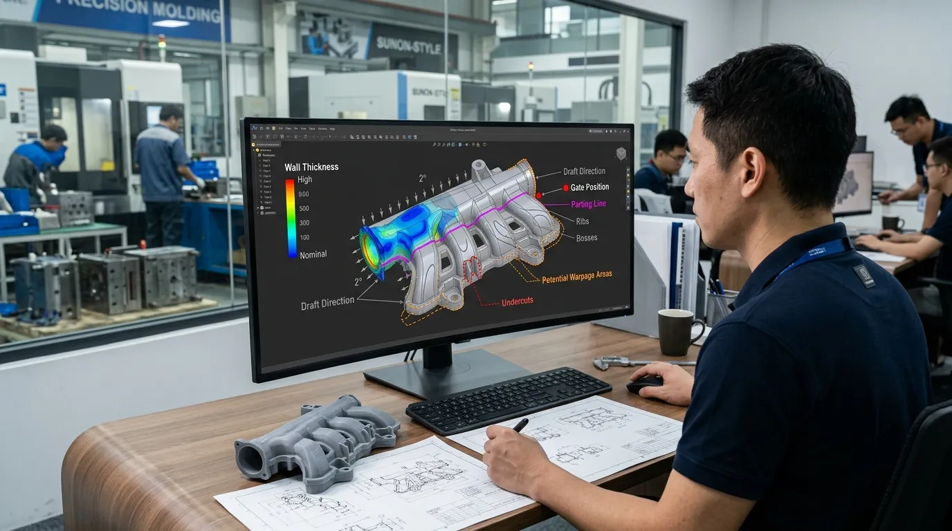
A reliable cooling-component mold begins with the part requirements, not with a standard mold layout. SunOn evaluates the areas most likely to affect moldability, dimensional stability, tool complexity, and sample approval.
Component Geometry and Assembly Interfaces
The mold must reproduce the features that control how the component fits and functions within the final assembly. During the initial review, SunOn evaluates:
- Critical dimensions and tolerances
- Mating and alignment surfaces
- Mounting or fastening features
- Clearance around nearby components
- Cosmetic and non-cosmetic surfaces
- Joining or assembly points
- Areas that require controlled flatness or positioning
Providing mating-part data can help identify potential interference, tolerance-stack, or assembly problems before tooling begins.
Wall Thickness, Ribs, Bosses, and Warpage Risk
Uneven wall thickness can cause different areas of a molded component to fill, pack, and cool at different rates. This may lead to sink marks, dimensional variation, internal stress, or warpage.
SunOn reviews thick transitions, ribs, bosses, and reinforced areas to determine whether the geometry can be improved without changing the component’s required function. Long, thin, flat, or asymmetrical parts may require additional attention because their shape can make distortion more difficult to control.
Detailed design principles are covered in SunOn’s plastic injection mold DFM guide.
Draft, Undercuts, and Part Release
Draft angles and ejection direction affect whether the molded part can leave the cavity without drag marks, deformation, or tool damage.
SunOn checks:
- Draft on vertical surfaces
- Deep pockets and narrow features
- Internal and external undercuts
- Ejector-pin locations
- Visible surfaces that should avoid marks
- Features that may require sliders or lifters
Where possible, a geometry change may simplify the mold. When an undercut is functionally necessary, the tooling can be designed with the required moving mechanism.
Material Shrinkage and Operating Conditions
Plastic resins shrink differently during cooling. The confirmed material must therefore be considered when determining cavity dimensions and evaluating expected part variation.
Buyers should provide:
- Selected or proposed resin
- Reinforcement, filler, or additives
- Expected operating-temperature range
- Chemical or coolant exposure, where applicable
- Required dimensional stability
- Functional and assembly conditions
SunOn does not apply one material assumption to every project. Mold design and validation requirements are reviewed against the actual resin and application.
| Design Requirement | Potential Tooling Risk | SunOn Review or Response |
|---|---|---|
| Uneven wall thickness | Sink, longer cooling, or warpage | Thickness and transition review |
| Limited draft | Difficult ejection or drag marks | Draft and release analysis |
| Undercuts | More complex mold movement | Redesign, slider, or lifter assessment |
| Critical mating dimensions | Assembly mismatch | Tolerance and inspection planning |
| Resin shrinkage | Out-of-spec dimensions | Cavity compensation based on confirmed material |
| Poor gate location | Weld lines, visible marks, or incomplete filling | Gate and filling analysis |
| Complex geometry | Uneven tool temperature | Mold-cooling and thermal-balance review |
| High production demand | Insufficient output or premature wear | Mold-steel and cavity-strategy review |
Mold Design Options Based on Your Production Requirements
The most suitable mold structure depends on more than part size. SunOn considers production demand, expected tool life, geometry, material, inspection requirements, and project stage before recommending a tooling route.
Rapid Tooling vs. Production Tooling
Rapid tooling may be suitable when the main objective is design validation, market testing, or limited production. A hardened production mold may be more appropriate for repeat orders, longer programs, abrasive materials, or higher output requirements.
The decision should be based on the complete project requirements rather than a fixed volume threshold.
Single-Cavity and Multi-Cavity Molds
A single-cavity mold can reduce initial tool complexity and may be practical for validation or lower production demand. Multi-cavity tooling can increase output but requires careful filling balance, consistent cooling, additional machining, and more detailed validation.
SunOn reviews:
- Forecast production volume
- Required output
- Part geometry
- Mold size
- Filling balance
- Dimensional consistency
- Tool maintenance requirements
Slides, Lifters, Inserts, and Advanced Tool Structures
Complex side features or undercuts may require sliders or lifters. Separate metal or plastic elements may require insert molding, while some projects may need multi-material or multi-cavity structures.
These mechanisms are added only when the component geometry or production plan justifies them. Unnecessary mold complexity can increase cost, maintenance, and adjustment time.
Mold Steel Selection
SunOn works with mold steels including P20, 718H, NAK80, H13, and S136. The appropriate grade depends on expected tool life, resin properties, surface requirements, corrosion considerations, polishing needs, and production conditions.
No single steel is best for every cooling-component mold.
| Project Requirement | Possible Tooling Route | Information Needed |
|---|---|---|
| Design validation | Prototype or rapid tooling | CAD, resin, sample quantity, and test requirements |
| Repeat production | Production mold | Annual volume, material, and tool-life expectations |
| Higher output | Multi-cavity mold | Demand forecast and output requirements |
| Complex undercuts | Slider or lifter mold | Geometry and ejection direction |
| Inserted components | Insert-molding tool | Insert material and positioning requirements |
| Tight assembly fit | Inspection-focused production tool | Critical dimensions and mating-part data |
SunOn’s Mold Development Process
1. CAD and Requirement Review
The project starts with 3D CAD files, 2D drawings, material information, production volume, critical dimensions, surface requirements, and application details.
2. DFM and Mold-Flow Review
SunOn evaluates wall thickness, draft, undercuts, gate position, parting lines, filling risks, shrinkage, ejection, and potential warpage. Mold-flow analysis may be used where it adds value to the project.
3. Mold Design Approval
The proposed mold layout can include the core, cavity, runner, gate, ejection system, slides, lifters, inserts, and cooling layout. Customer approval is required before tool manufacturing begins.
4. Mold Manufacturing
Approved mold components are produced using suitable machining processes such as milling, turning, grinding, and EDM. Individual components are checked before assembly.
5. Mold Assembly
The mold is fitted and assembled. Alignment, movement, shut-off areas, and mechanical functions are checked before the first trial.
6. Trial Molding and T1 Samples
The first mold trial produces T1 samples for review. The customer can assess dimensions, appearance, assembly fit, and other agreed acceptance requirements.
7. Mold Tuning and Approval
Feedback from T1 inspection is used to identify required tool or process changes. The mold may be adjusted and sampled again until the agreed requirements are met.
8. Production or Tool Delivery
After approval, the project can continue into molded-part production, finishing, assembly, or packaging with SunOn. Buyers who need additional process context can review the full plastic injection molding process.
T1 Sample Validation and Quality Control
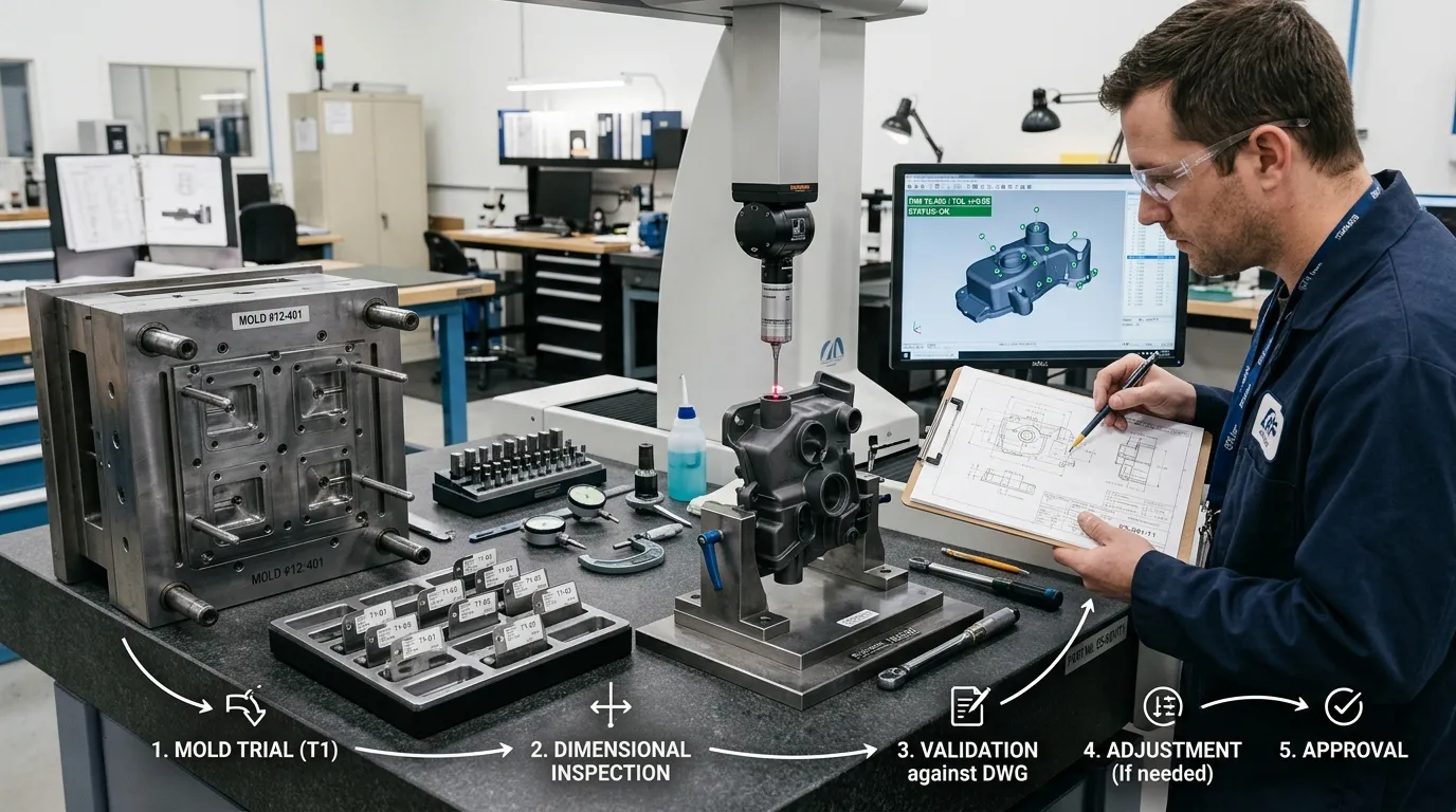
T1 approval is an important stage between tool construction and production release. SunOn evaluates the initial molded samples against the agreed drawings and project requirements.
Validation may include:
- Dimensional inspection
- Critical-dimension reporting
- Visual and surface inspection
- Assembly-fit checks
- Functional testing when the customer provides a method
- Material verification where required
- Review of filling, ejection, and visible defects
- Identification of corrective actions
- Resampling after tool adjustment
Inspection methods may include CMM and optical measurement, depending on the component geometry and tolerance requirements.
The final inspection plan should be agreed before tooling starts. Buyers should clearly mark critical dimensions, functional interfaces, and acceptance criteria on their drawings.
Why Work With SunOn for Cooling-Component Tooling?
SunOn supports the project from design review through mold construction, trial, adjustment, and production. This integrated workflow helps reduce communication gaps between engineering, toolmaking, sampling, and molding.
Key capabilities include:
- In-house mold design and fabrication
- DFM review before steel cutting
- Mold-flow support where required
- Trial and T1 sample production
- Dimensional inspection
- Tool tuning after customer feedback
- Optional injection molding and downstream services
- Experience supporting custom manufacturing projects
- Quality-management and inspection systems
The tooling proposal is developed around the specific component rather than a standard package. Final mold structure, steel, cavity count, testing, and production support depend on the submitted design and requirements.
What to Send for a Tooling Quote
Providing complete project information allows SunOn to review moldability and prepare a more accurate proposal.
Send:
- 3D CAD file
- 2D drawing
- Selected or proposed plastic material
- Prototype quantity, if required
- Expected production quantity
- Estimated annual demand
- Critical dimensions and tolerances
- Mating-part or assembly information
- Surface-finish requirements
- Color requirements, where relevant
- Operating-temperature range
- Chemical or coolant exposure, where applicable
- Functional tests or acceptance criteria
- Required T1 sample quantity
- Target project schedule
- Expected tool life, if defined
Tooling lead time depends on component geometry, mold complexity, steel, cavity count, material, testing requirements, and the number of sampling or adjustment stages.
Frequently Asked Questions
What files are required for a cooling-component injection mold quote?
Send a 3D CAD file, 2D drawing, material specification, expected production volume, critical tolerances, surface requirements, and application information. Mating-part data is also useful when assembly fit is important.
Does SunOn provide DFM before mold manufacturing?
Yes. SunOn reviews moldability, wall thickness, draft, undercuts, gate position, parting lines, shrinkage, ejection, and other tooling risks before mold manufacturing begins.
Can SunOn build both prototype and production molds?
Yes. The suitable tooling route depends on the project stage, resin, geometry, expected volume, required tool life, and validation needs.
How are T1 cooling-component samples inspected?
T1 samples can be checked for dimensions, appearance, assembly fit, and agreed functional requirements. Critical dimensions should be identified before mold construction so the inspection plan can be prepared correctly.
Can SunOn manufacture molded parts after completing the tool?
Yes. SunOn can continue from approved tooling into injection-molding production and may also support finishing, assembly, packaging, and related downstream work.
How is mold steel selected?
Mold steel is selected according to resin, expected tool life, production demand, surface requirements, corrosion risk, wear, and maintenance needs.
What factors determine tooling lead time?
Lead time depends on mold complexity, part geometry, steel, cavity count, sliders or lifters, inspection requirements, trial results, and the number of adjustments required after sampling.
Can design changes be made after the first mold trial?
Yes, but the type and scale of the change determine whether the mold can be adjusted or whether major components must be remade. Reviewing manufacturability before steel cutting helps reduce expensive late changes.
Upload your cooling-component design for a DFM review and custom tooling quotation. Send SunOn your CAD files, material, expected volume, critical dimensions, assembly requirements, and operating conditions to begin the moldability review.
