


Molded Cooling Components: Custom Injection Molding Services from SunOn
Molded cooling components are custom injection-molded plastic parts designed for cooling and fluid-management assemblies. These may include protective housings, mounting brackets, covers, supports, connector bodies, and molded manifold bodies.
SunOn provides custom mold design, tooling, injection molding, secondary processing, inspection, assembly, and production support for these components. Every part is manufactured according to the customer’s drawings, operating conditions, material requirements, tolerances, and expected production volume.
Send SunOn your 2D drawings, 3D CAD files, material requirements, operating conditions, and annual volume to request a DFM review and custom quotation.
Custom Molded Cooling Components from SunOn
SunOn manufactures custom plastic components for equipment manufacturers, engineering teams, and cooling-system integrators. The service covers both injection mold development and molded-part production, allowing buyers to manage tooling, sampling, manufacturing, and secondary operations through one supplier.
Depending on the project, SunOn can provide:
- Injection mold design and manufacturing
- Design for manufacturability review
- Material and tooling evaluation
- T1 and approval samples
- Single-cavity or multi-cavity production molds
- Custom injection-molded components
- Insert molding and overmolding
- Threaded insert installation
- Trimming and deflashing
- Surface finishing
- Ultrasonic welding and secondary joining
- Component or subassembly production
- Dimensional and visual inspection
- Assembly, packaging, and delivery
SunOn’s broader custom injection molding services support projects from initial design review through mold manufacturing and repeat production.
These are custom manufacturing services rather than stocked cooling products. Component geometry, resin, tooling structure, inspection standards, and production methods are determined from the buyer’s technical requirements.
Types of Molded Components for Cooling Assemblies
Cooling assemblies often contain plastic parts that protect equipment, position hardware, support tubing, organise interfaces, or distribute fluid. The suitability of each component for injection molding depends on its geometry, operating environment, load, sealing requirements, and production volume.
Plastic Housings and Enclosures
Plastic housings protect and position pumps, sensors, control units, fans, connectors, tubing interfaces, and other parts within a cooling assembly.
A custom housing may include:
- Mounting bosses
- Structural ribs
- Snap-fit features
- Cable or tube openings
- Sensor interfaces
- Threaded inserts
- Removable covers
- Internal guides
- Labels, textures, or identification marks
During DFM, SunOn reviews wall thickness, draft angles, boss design, rib placement, undercuts, parting lines, ejection areas, and expected shrinkage. Critical mounting and assembly surfaces should be clearly identified in the drawing so they can receive the appropriate dimensional control.
Molded Mounting Brackets and Supports
Injection-molded brackets can position pumps, fans, tubes, sensors, electronic modules, and other cooling-system hardware.
Important project requirements may include:
- Static and dynamic loads
- Mounting-hole positions
- Required stiffness
- Vibration exposure
- Fastener type
- Insert pull-out strength
- Operating temperature
- Chemical or moisture exposure
- Assembly tolerances
Ribs, gussets, bosses, and metal inserts may be used to strengthen the part without creating unnecessarily thick plastic sections. Resin selection should also consider long-term creep when the bracket remains under continuous load.
Molded Manifold and Flow-Distribution Bodies
A molded manifold body may combine several ports, channels, connection points, or mounting features into one component. This can reduce part count and simplify assembly when the design is suitable for injection molding.
These projects require detailed technical information, including:
- Fluid or coolant type
- Operating temperature
- Working pressure
- Port geometry
- Flow-path design
- Sealing method
- Insert or thread requirements
- Critical surface tolerances
- Inspection and testing requirements
Gate position, weld lines, core design, shrinkage, sealing surfaces, and dimensional stability must be considered before mold manufacturing.
SunOn should evaluate each manifold project individually. Pressure capability, leak performance, coolant compatibility, and validation methods depend on the selected material, component design, molding process, and customer-defined testing requirements.
Covers, Guides, Fittings, and Auxiliary Parts
SunOn can also evaluate related molded parts such as protective covers, tube guides, connector bodies, clips, guards, supports, and fitting housings.
These parts may appear simple, but their performance can depend on snap-fit geometry, assembly force, impact resistance, fastening method, surface finish, and dimensional repeatability.
| Component Category | Typical Role | Information Required from Buyer | Important Molding Considerations |
|---|---|---|---|
| Housing or enclosure | Protects and positions cooling-system hardware | CAD files, mounting details, openings, environment and annual volume | Wall thickness, ribs, bosses, draft, inserts and warpage |
| Mounting bracket | Supports pumps, fans, sensors, tubing or assemblies | Load, mounting pattern, vibration, tolerances and hardware | Stiffness, creep, ribs, resin and insert strength |
| Manifold body | Distributes fluid between defined ports | Fluid, temperature, pressure, ports, seals and test requirements | Core design, weld lines, sealing faces and shrinkage |
| Cover or guard | Protects parts or controls access | Fit, fastening method, appearance and environment | Snap-fits, bosses, texture, draft and parting line |
| Fitting or connector body | Connects tubing or other components | Interface dimensions, media, force and sealing method | Material compatibility, tolerances, inserts and surface quality |
Material Selection for Molded Cooling-System Components
Material selection should begin with the component’s real operating conditions, not only its shape or target price.
The engineering review may consider:
- Maximum and minimum operating temperatures
- Coolant, oil, water, detergent, or chemical exposure
- Moisture absorption
- Required stiffness and strength
- Impact resistance
- Creep under continuous load
- Dimensional stability
- Electrical insulation requirements
- Flame-retardancy requirements
- UV exposure
- Surface appearance
- Expected service life
- Production volume and cost objectives
SunOn processes commonly used thermoplastic families such as ABS, PC, nylon, PP, POM, PET, PC/ABS, and PE. However, not every resin is suitable for coolant contact, elevated temperatures, pressure-bearing designs, or long-term structural loading.
Final material selection should be based on the customer’s technical specifications, chemical environment, regulatory requirements, mechanical loads, and required service life. Material data and application requirements should be reviewed before tooling begins.
DFM for Cooling Housings, Brackets, and Manifold Bodies
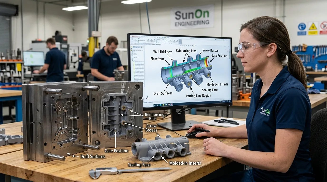
A detailed injection mold DFM review helps identify manufacturing risks before the mold is built. This is especially important for functional cooling components with mounting interfaces, sealing areas, inserts, ports, or internal flow features.
Wall Thickness and Transitions
Consistent wall thickness supports more uniform filling, cooling, and shrinkage. Sudden changes between thick and thin sections can contribute to sink marks, voids, warpage, or longer molding cycles.
Where additional strength is needed, ribs or gussets may be more effective than simply increasing the full wall thickness.
Ribs, Bosses, and Mounting Features
Ribs can improve stiffness while reducing material use. Bosses may support screws, inserts, or alignment features.
Their size and position should be reviewed carefully because heavy sections around bosses and ribs may create visible sink marks or uneven shrinkage. Mounting features must also be designed for the actual assembly load rather than appearance alone.
Draft, Parting Lines, and Ejection
Draft angles help the molded component release from the tool without damage. Parting lines and ejector locations should be positioned away from critical cosmetic, sealing, or assembly surfaces whenever possible.
Undercuts, side actions, and internal features can increase mold complexity. SunOn reviews whether these features are necessary or whether the geometry can be simplified.
Gates, Weld Lines, and Sealing Regions
Gate position affects filling behaviour, appearance, weld-line formation, and part stability. For housings or manifold bodies, weld lines should be evaluated around ports, holes, inserts, and stressed areas.
The customer should clearly mark sealing faces and other critical functional regions in the drawing. These surfaces may require tighter dimensional or appearance controls than non-critical areas.
Inserts and Secondary Assembly
Threaded inserts, bushings, pins, or other metal elements may be incorporated through insert molding or installed after molding.
Depending on the design, secondary operations may also include:
- Heat staking
- Ultrasonic welding
- Mechanical fastening
- Adhesive joining
- Secondary machining
- Component assembly
The most suitable approach depends on required strength, production volume, serviceability, tolerance, and cost.
SunOn’s Process from CAD Review to Production
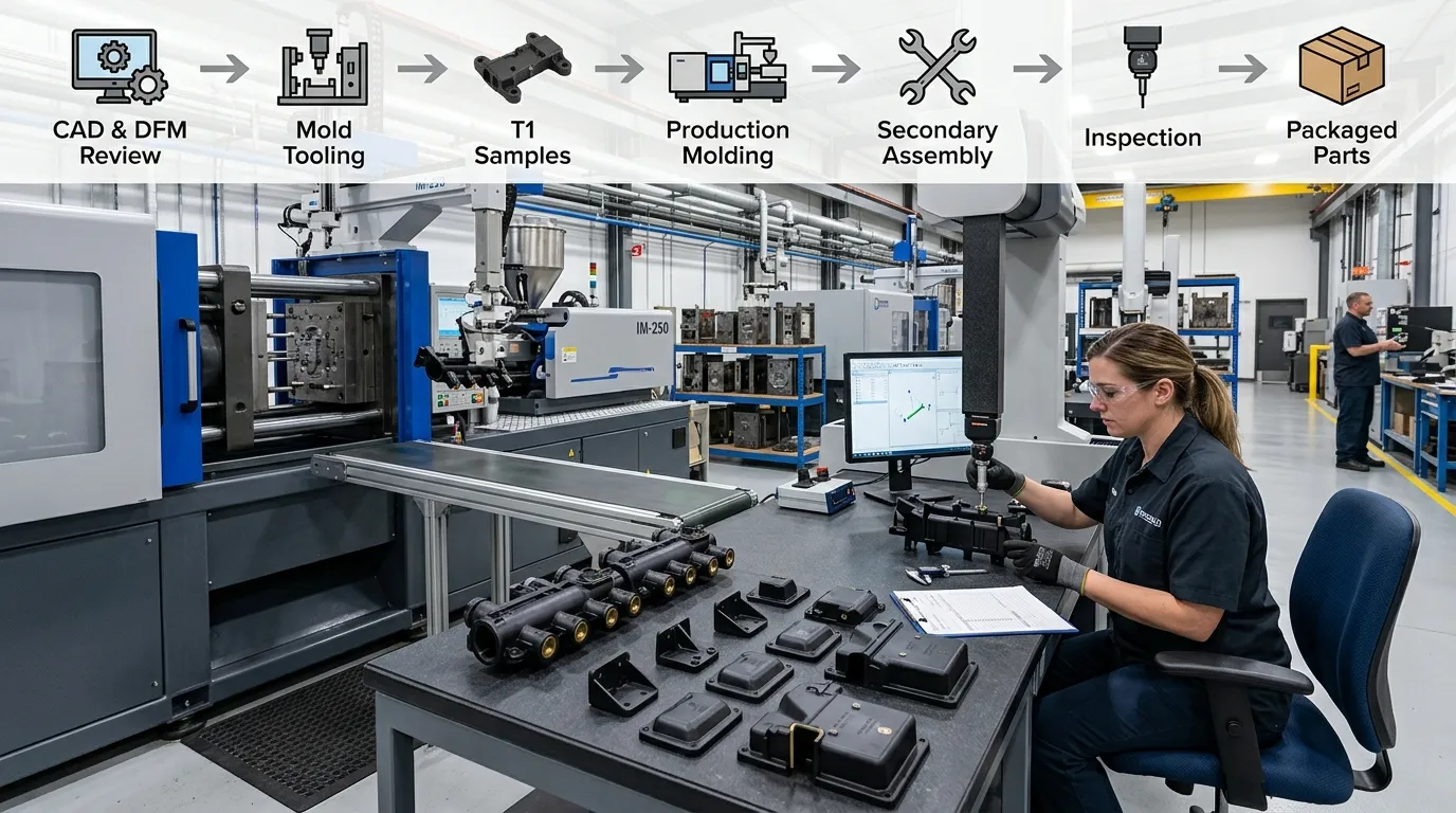
SunOn follows a structured development process for custom injection-molded cooling components.
RFQ and technical-file review
The customer provides 2D drawings, 3D CAD models, material or performance requirements, estimated quantities, finishes, tolerances, and inspection requirements.
Feasibility and DFM review
SunOn reviews geometry, draft, wall thickness, undercuts, ribs, bosses, gate strategy, parting lines, shrinkage, warpage risk, material requirements, and expected production volume.
Mold design and approval
The mold structure is developed based on the component geometry and production needs. This may include cavity planning, inserts, side actions, ejection, cooling, and gating arrangements.
Mold manufacturing
Tool components are machined, fitted, assembled, and prepared for the first molding trial.
T1 samples
Initial samples are produced for dimensional, visual, assembly, and functional evaluation. Customer feedback is used to determine whether mold adjustment or process optimisation is required.
Production molding
After sample approval, the project moves into the agreed production stage. Material preparation, machine settings, cycle conditions, part handling, and process controls are established for repeat manufacturing.
Secondary processing and assembly
Parts may receive trimming, deflashing, finishing, insert installation, welding, joining, printing, machining, assembly, or packaging according to the project scope.
Inspection and delivery
Completed parts are checked against the drawing and agreed quality requirements before packaging and shipment.
For a more detailed explanation of each production stage, review SunOn’s plastic injection molding process.
Quality Requirements for Functional Cooling Components
Cooling-system components often connect with other parts, mounting points, ports, tubes, seals, or fasteners. Small dimensional variations can affect fit, alignment, assembly, or function.
The quality plan may include checks for:
- Critical dimensions
- Mounting-hole positions
- Flatness
- Port geometry
- Insert location
- Sealing surfaces
- Surface appearance
- Part weight
- Assembly fit
- Material identification
- Customer-defined functional requirements
SunOn can use dimensional, visual, and functional inspection according to the project specification. Inspection equipment and reporting requirements should be confirmed during quotation.
Pressure testing, leak testing, thermal cycling, coolant-aging tests, IP validation, or other specialised testing must be defined by the customer and confirmed as part of the project scope. Test conditions, acceptance criteria, sample quantities, and documentation requirements should be agreed before production.
Why Source Molded Cooling Components from SunOn?
SunOn supports custom projects from mold engineering through molded-part production. This integrated model helps reduce communication gaps between the tooling supplier and the production molder.
Buyers can work with SunOn for:
- Early manufacturability review
- Custom mold design and manufacturing
- Material and process evaluation
- T1 sample production
- Mold adjustment and approval
- Repeat injection molding
- Insert molding and overmolding
- Secondary processing
- Dimensional and visual inspection
- Assembly and packaging
For technically demanding parts, SunOn can review mounting features, ports, inserts, sealing regions, wall thickness, ribs, bosses, draft, and potential warpage before tooling begins.
Actual component photographs, inspection records, material documentation, test reports, or project examples can be discussed during supplier evaluation when they are available and relevant to the requested project.
Information Needed for a Molded Cooling Component Quote
Providing complete project information helps SunOn evaluate manufacturability, tooling structure, material needs, inspection scope, and production cost more accurately.
Include the following with your RFQ:
- 3D CAD file
- 2D technical drawing
- Description of the component’s function
- Preferred material or required material properties
- Coolant or chemical exposure
- Operating temperature range
- Pressure requirements, where applicable
- Mechanical loads
- Sealing method
- Critical dimensions and tolerances
- Inserts or embedded hardware
- Surface finish and colour
- Initial order quantity
- Estimated annual volume
- Inspection or validation requirements
- Assembly and packaging needs
- Target project schedule
Upload your files and requirements to request a manufacturability review and project-specific quotation.
Frequently Asked Questions
What are molded cooling components?
Molded cooling components are custom injection-molded plastic parts used within cooling or fluid-management assemblies. They may include housings, brackets, covers, supports, connector bodies, and manifold bodies. They are different from the cooling channels and hardware installed inside an injection mold.
Which types of cooling-system plastic parts can SunOn quote?
SunOn can evaluate custom housings, enclosures, brackets, supports, covers, guides, fitting bodies, connector bodies, and molded manifold designs. Final feasibility depends on the part geometry, material requirements, operating conditions, tolerances, expected volume, and validation needs.
Can SunOn manufacture both the mold and the molded components?
Yes. SunOn provides custom injection mold design and manufacturing together with trial sampling and production molding. Secondary processing, insert installation, assembly, inspection, and packaging may also be included depending on the project.
Which materials are used for molded cooling-system components?
Possible materials include ABS, PC, nylon, PP, POM, PET, PC/ABS, PE, and other engineering thermoplastics. The appropriate resin depends on temperature, chemical exposure, moisture, pressure, structural load, flame requirements, dimensional stability, and service-life expectations.
Can SunOn mold threaded metal inserts into a housing or bracket?
Yes, threaded inserts or other metal elements may be incorporated through insert molding or installed after molding. The appropriate method depends on pull-out strength, torque, part geometry, production volume, tolerance, and assembly requirements.
Can SunOn manufacture a molded plastic manifold body?
SunOn can review custom manifold-body designs for injection molding. The customer must provide fluid type, operating temperature, pressure, port geometry, sealing method, material requirements, critical dimensions, and testing criteria. Feasibility and validation requirements are determined for each project.
What files are required for a quotation?
A 3D CAD model and 2D drawing are preferred. The RFQ should also include material requirements, operating conditions, tolerances, expected quantities, surface finish, inserts, inspection standards, testing requirements, and any assembly or packaging needs.
How are molded cooling components inspected?
Inspection may include dimensional measurements, visual checks, insert verification, assembly-fit checks, and customer-defined functional criteria. Critical characteristics and required reports should be identified during quotation so the correct inspection plan can be established.
Can SunOn provide post-processing and assembly?
Depending on the project, SunOn can support trimming, deflashing, surface finishing, printing, secondary machining, threaded insert installation, ultrasonic welding, joining, component assembly, packaging, and other agreed secondary operations.
What affects mold-development and production lead time?
Lead time depends on part complexity, mold structure, cavity count, resin, side actions, inserts, surface requirements, inspection scope, sample revisions, and production volume. SunOn reviews these factors after receiving the technical files and provides a project-specific schedule.
Send SunOn your 2D drawing, 3D CAD model, operating conditions, material or performance requirements, annual volume, tolerances, finish, and testing requirements to request a DFM review and custom quotation for your molded cooling components.
