


CMM-Inspected CNC Parts: GD&T, Reports, and RFQ Guide
CMM-inspected CNC parts are custom-machined components whose specified dimensions or geometric characteristics have been verified using a coordinate measuring machine.
For engineers and technical buyers, however, the phrase “CMM inspected” is not a complete quality requirement. It does not explain which dimensions will be measured, how the part will be aligned, whether inspection applies to the first article or every part, or what report will be delivered.
A useful inspection plan should connect the engineering drawing, functional datums, critical-to-quality features, measurement method, sampling level, acceptance criteria, and required documentation.
SunOn supports custom CNC machining services with dimensional inspection requirements defined according to customer drawings and RFQ specifications.
CMM-Inspected CNC Parts at a Glance
| Buyer Requirement | Recommended Direction |
|---|---|
| Complex feature relationships | Consider CMM inspection |
| Position, profile, flatness, or perpendicularity | Define datums and GD&T clearly |
| Prototype validation | Request first-article inspection |
| Repeat production | Define sampling or full inspection |
| Small simple dimensions | Manual gauges may be sufficient |
| Sensitive or flexible surfaces | Review tactile or optical measurement |
| Surface roughness requirement | Specify a roughness instrument separately |
| Internal thread acceptance | Use suitable thread gauges where appropriate |
| Formal inspection records | Define report format before quotation |
| Very tight tolerances | Review measurement uncertainty and environment |
What Does CMM Inspection Mean?
A coordinate measuring machine measures points on a physical component within an X, Y, and Z coordinate system. The inspection software uses these measured points to construct features such as:
- Planes
- Lines
- Circles
- Cylinders
- Cones
- Slots
- Hole patterns
- Contoured surfaces
The resulting features can then be compared with the engineering drawing or nominal CAD geometry.
Hexagon’s introduction to coordinate metrology explains that the measured points are combined into features that can be related to one another within the same coordinate system.
CMMs may use:
- Touch-trigger probes
- Scanning probes
- Optical sensors
- Laser sensors
- Multi-sensor systems
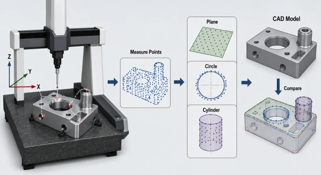
The correct sensor depends on the part material, feature size, accessibility, surface condition, and required measurement.
What Can a CMM Verify?
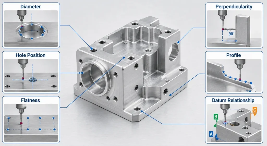
When the machine, probe, fixture, program, and alignment strategy are suitable, CMM inspection can support verification of:
Size
Examples include:
- Hole diameter
- Outside diameter
- Slot width
- Distance between features
- Wall thickness where accessible
Location
A CMM can evaluate whether a hole, slot, boss, or other feature is positioned correctly relative to the defined datums.
Orientation
Possible checks include:
- Parallelism
- Perpendicularity
- Angularity
Form
Depending on the measurement strategy, a CMM may evaluate:
- Flatness
- Straightness
- Circularity
- Cylindricity
Profile and Complex Geometry
Scanning or multi-sensor inspection may be used to compare contoured surfaces with nominal CAD data.
For components with multi-face or rotational geometry, SunOn’s CNC turning and milling services page explains why feature relationships and datum references should be communicated before machining begins.
CMM Inspection Does Not Replace Every Measurement Method
A CMM is a flexible dimensional inspection tool, but it is not automatically the best method for every characteristic.
| Inspection Requirement | Commonly Considered Method |
|---|---|
| Complex GD&T relationships | CMM |
| Simple outside dimension | Micrometer or caliper |
| Precision bore | Bore gauge, air gauge, or CMM |
| Internal and external threads | Thread plug or ring gauge |
| Surface roughness | Roughness tester |
| Coating thickness | Coating-thickness gauge |
| Material composition | Material verification method |
| Hardness | Hardness tester |
| Internal porosity | X-ray or CT where required |
| Leak integrity | Pressure or leak test |
| Assembly fit | Functional gauge or assembly test |
The inspection method should match the characteristic being verified. A part described as CMM inspected may still require thread gauges, roughness measurement, visual inspection, material certificates, or functional testing.
Start with the Drawing and Datum System
Reliable CMM inspection begins with a controlled engineering drawing.
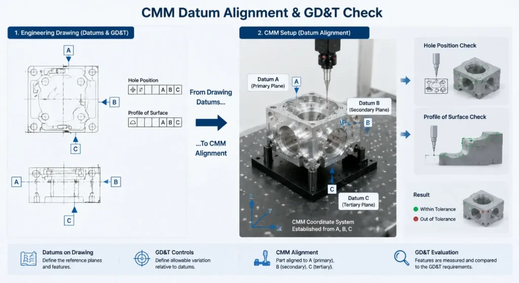
The drawing should clearly identify:
- Datum features
- Basic dimensions
- Dimensional tolerances
- GD&T callouts
- Fits
- Thread requirements
- Surface roughness
- Cosmetic zones
- Inspection notes
- Applicable drawing standard
A datum is not simply the surface that is easiest to reach with the probe. It represents the functional reference used to locate and orient the part during design, assembly, and inspection.
An unclear datum system can lead to several problems:
- The supplier and customer align the part differently
- Hole-position results vary between inspection programs
- Profile results do not reflect actual assembly conditions
- A dimension passes in one setup but fails in another
- Inspection reports become difficult to compare
When functional datums are difficult to fixture or probe, the measurement strategy should be reviewed before production.
First Article, In-Process, and Final Inspection
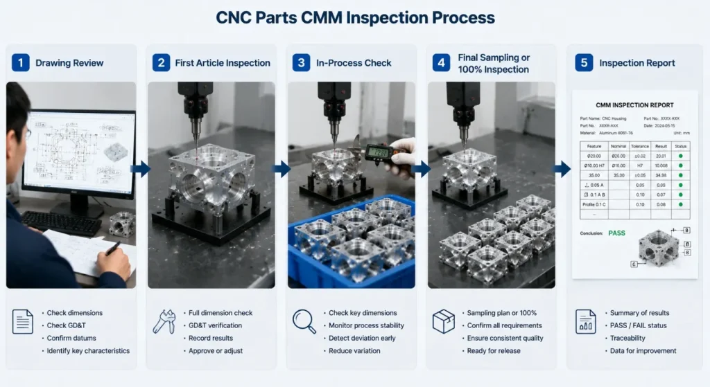
“CMM inspected” should specify when inspection occurs.
First-Article Inspection
First-article inspection verifies an initial part or initial production sample against the drawing before repeat production continues.
It is particularly useful for:
- New CNC programs
- New fixtures
- Revised drawings
- New materials
- Supplier transfers
- Complex GD&T
- High-value components
First-article inspection does not automatically prove that every later part will remain compliant. The production process still requires suitable controls.
In-Process Inspection
In-process checks help identify drift before an entire batch is completed.
These checks may focus on:
- Tool-wear-sensitive dimensions
- Bore size
- Flatness
- Part location
- Features completed before re-fixturing
- Dimensions affected by heat treatment or finishing
Machine-tool probing can also support setup and process control, but it should not automatically be treated as an independent replacement for final inspection.
Final Inspection
Final inspection verifies the completed component after all relevant machining and secondary processes.
The buyer should state whether final CMM inspection applies to:
- One first article
- A defined sample
- Each production batch
- A percentage of the order
- Every delivered part
- Only selected critical characteristics
Sampling Inspection vs. 100% CMM Inspection
Not every CNC project requires every part to be fully measured on a CMM.
Sampling May Be Appropriate When
- The process is stable
- Fixtures and tooling are controlled
- Part value is moderate
- Critical features are monitored in process
- The order quantity is high
- The customer accepts an agreed sampling plan
Full Inspection May Be Required When
- The part is safety- or mission-critical
- Batch quantities are low
- Each component has high value
- Tolerances are particularly demanding
- Traceability is required for each serial number
- Contract documents require 100% verification
Even when 100% CMM inspection is requested, the buyer should clarify whether this means every drawing dimension or only a defined list of critical characteristics.
Full measurement of every non-critical dimension may add inspection time and cost without improving the functional reliability of the part.
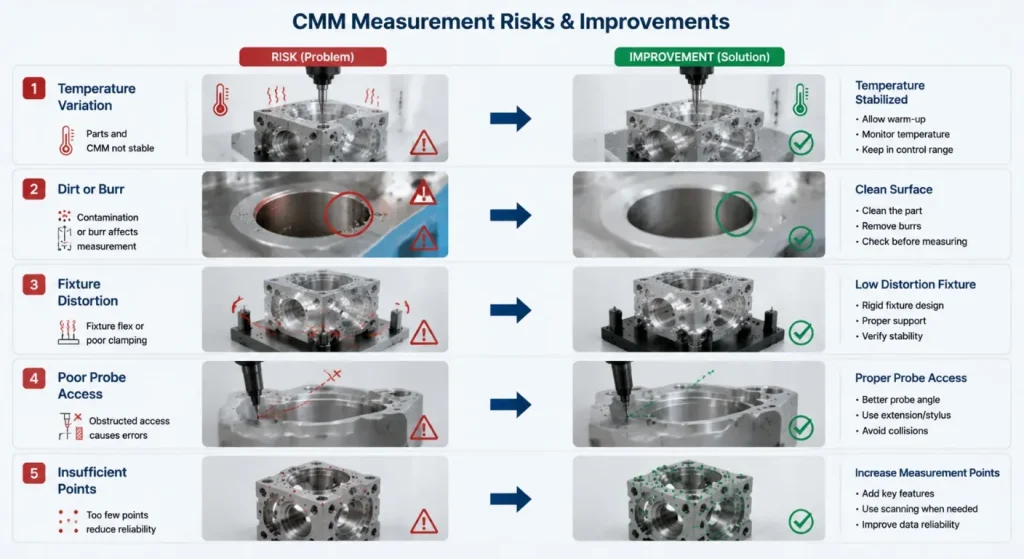
Factors That Affect CMM Measurement Results
A CMM report should not be treated as independent of the measurement process.
Part Temperature
Machined parts can change dimension as their temperature changes. Parts should be allowed to stabilize where temperature could materially affect the result.
Cleanliness
Oil, chips, dust, burrs, and coating residue may affect probe contact or prevent stable fixturing.
Fixturing
The fixture should locate the component without deforming it or blocking required features.
This is especially important for:
- Thin-wall aluminum parts
- Flexible plastic components
- Slender shafts
- Sheet-like plates
- Soft materials
Probe Access
A probe must be able to reach the feature at an appropriate angle. Deep bores, narrow slots, undercuts, and closely spaced walls may require special styli, repositioning, optical measurement, or a different inspection method.
Point Density
A small number of measured points may not adequately represent a surface with form variation.
The number and distribution of points should reflect the feature and the purpose of the measurement.
Measurement Uncertainty
Every measurement has uncertainty. NIST’s CMM measurement uncertainty report discusses how the machine, probe, workpiece, environment, and measurement strategy can influence results.
For very tight tolerances, the inspection method should be capable enough to distinguish meaningful part variation from measurement variation.
CMM Performance and Verification
A buyer should avoid evaluating a supplier only by the brand or size of its CMM.
Important considerations include:
- Machine measuring volume
- Probe and stylus configuration
- Calibration and verification status
- Environmental control
- Software and reporting capability
- Operator and programmer competence
- Part-fixturing strategy
- Measurement uncertainty
- Suitability for the specific feature
The ISO 10360 series addresses acceptance and reverification testing for coordinate measuring systems and their probing configurations.
ZEISS also provides an overview of coordinate measuring machines for different workpiece sizes, sensors, and measurement environments.
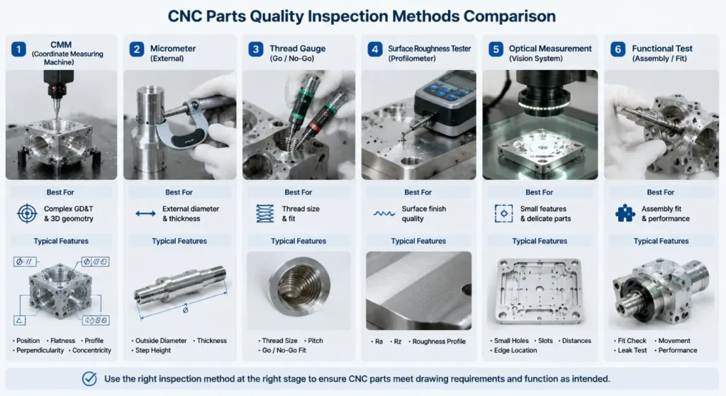
A supplier should confirm that the available system is suitable for the specific part rather than relying on a general claim that it owns a CMM.
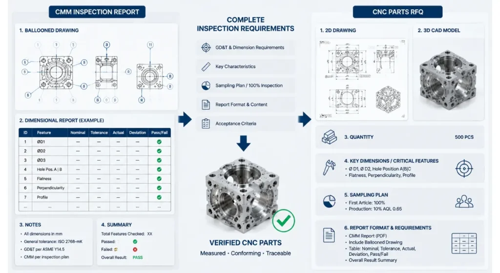
What Should a CMM Inspection Report Include?
A useful report may contain:
- Customer part number
- Drawing revision
- Part or serial number
- Inspection date
- Material or batch reference
- Measured characteristic
- Nominal value
- Upper and lower limits
- Actual measured value
- Deviation
- Pass or fail result
- Datum reference
- Units
- Inspector or report identifier
For complex parts, additional content may include:
- Ballooned drawing
- Feature map
- Alignment description
- Probe or sensor information
- CAD comparison
- Graphic GD&T results
- Serial-number traceability
- Measurement program revision
The report format should be agreed before quotation. A simple dimensional table, first-article report, full GD&T report, and graphical CAD comparison involve different levels of programming and reporting effort.
Buyers evaluating supplier documentation can also review SunOn’s ISO 9001 CNC machining supplier checklist.
When Should Buyers Request CMM Inspection?
CMM inspection is especially useful for CNC parts containing:
- Multiple related datums
- Complex hole patterns
- Profile tolerances
- Multi-face geometry
- Precision bores
- Sealing surfaces
- Bearing locations
- Assembly-critical interfaces
- Difficult-to-measure angular features
- High-value or performance-critical components
SunOn’s aerospace CNC machining page provides an example of projects where dimensional reporting and first-article inspection may be specified alongside machining requirements.
For simple spacers, washers, or non-critical brackets, manual gauges may provide a more efficient inspection route.
From RFQ to CMM-Inspected CNC Parts
A controlled project commonly follows these stages:
- Drawing Review: Confirm revision, datums, tolerances, GD&T, and critical characteristics.
- Inspection Planning: Select CMM, manual, optical, surface, and functional checks.
- DFM Review: Identify features that are difficult to machine, fixture, or inspect.
- CNC Programming: Plan operations around functional datums and process control.
- First-Part Machining: Produce the initial component.
- First-Article Inspection: Verify selected or complete drawing requirements.
- Production Control: Monitor tool wear and process-sensitive dimensions.
- Final Inspection: Complete the agreed sampling or full-inspection plan.
- Reporting and Packaging: Deliver the required records with protected parts.
What to Include in the RFQ
For an accurate quotation, provide:
- Controlled 2D engineering drawing
- 3D CAD model
- Drawing revision
- Material and material condition
- Prototype and production quantities
- Datum scheme
- Critical dimensions and GD&T
- Surface finish requirements
- Thread specifications
- Secondary processes
- First-article requirements
- Sampling or 100% inspection requirements
- Required CMM report format
- Ballooned drawing requirements
- Serial-number traceability
- Material and process certificates
- Packaging and delivery requirements
SunOn’s CNC machining quotation guide provides additional guidance on preparing drawings, tolerances, inspection notes, and project information.
Frequently Asked Questions
1. Does CMM Inspection Mean Every Dimension Is Checked?
Not necessarily. CMM inspection may cover selected critical characteristics, a complete first article, or every drawing dimension depending on the purchase requirements. The scope should be defined before quotation.
2. Does CMM Inspection Mean Every CNC Part Is Measured?
No. Inspection may apply to a first article, batch sample, defined percentage, or every delivered part. Buyers should clearly state the required sampling level or 100% inspection requirement.
3. Can a CMM Measure All CNC Part Features?
A CMM can measure many sizes and geometric relationships, but probe access, feature size, material flexibility, surface condition, and part geometry can limit the method. Threads, roughness, hardness, coating thickness, and leak integrity often require other inspection tools.
4. What Is the Difference Between CMM Inspection and First-Article Inspection?
CMM is a measurement technology, while first-article inspection is an inspection stage and documentation process. A CMM may be used during first-article inspection, but FAI can also include gauges, material records, surface checks, and functional tests.
5. What Should Be Included in a CMM Report?
A useful report should show the drawing revision, measured feature, nominal value, tolerance limits, actual result, deviation, and pass/fail status. Complex projects may also require a ballooned drawing, datum references, serial numbers, and graphical GD&T results.
6. Does a Passing CMM Report Guarantee That the Part Will Work?
A passing report confirms that the inspected characteristics met the stated requirements under the measurement conditions. It does not automatically verify material performance, surface integrity, cleanliness, leak resistance, or assembly function unless those requirements were also tested.
Conclusion
CMM-inspected CNC parts are not defined only by the use of a coordinate measuring machine. Reliable verification depends on the drawing, datum system, measurement strategy, fixture, probe access, environmental conditions, sampling plan, and report requirements.
A CMM can verify complex dimensional and geometric relationships, but it should be combined with thread gauges, roughness measurement, material documentation, visual checks, or functional testing where those methods better match the requirement.
Buyers should specify which features require CMM inspection, when inspection should occur, how many parts must be checked, and which documents must accompany the order.
To request a manufacturability and inspection review, contact SunOn with your 2D drawing, 3D CAD model, quantity, critical characteristics, CMM-report requirements, and delivery needs.
