


High-Accuracy CNC Machining: Tolerances, GD&T, and RFQ GuideSEO Title
High-accuracy CNC machining is used when the dimensions and geometric relationships of a custom component directly affect fit, motion, sealing, alignment, load transfer, or product performance.
However, “high accuracy” is not a universal tolerance class. A tolerance suitable for a small precision bore may be unrealistic for a large thin-wall housing, heat-treated steel component, or temperature-sensitive plastic part.
Accuracy also depends on more than the CNC machine. Material behavior, datum selection, workholding, tool condition, operation sequence, thermal stability, surface finishing, and inspection capability all affect the final result.
For engineers and technical buyers, the key question is therefore not:
How accurate is the machine?
A more useful question is:
Which part features must be controlled, how will they be manufactured, and how will compliance be verified?
SunOn supports custom CNC machining services based on customer drawings, CAD files, materials, tolerance requirements, finishes, and inspection plans.
High-Accuracy CNC Machining at a Glance
| Project Requirement | Recommended Direction |
|---|---|
| General non-critical dimensions | Use a suitable general tolerance |
| Shaft, bore, bearing, or sealing fit | Define individual limits and surface finish |
| Related holes or multi-face features | Use functional datums and GD&T |
| Complex features on several sides | Review setup reduction or multi-axis machining |
| Thin-wall or flexible component | Review clamping, distortion, and inspection |
| Heat-treated or stress-sensitive material | Plan roughing, stabilization, and finishing |
| Tight dimensions after coating | Define whether inspection occurs before or after finishing |
| Repeat production | Identify process-sensitive dimensions and sampling |
| Formal quality documentation | Define report type before quotation |
| Very tight tolerance | Confirm measurement method and uncertainty |
What Does High Accuracy Mean in CNC Machining?
In practical manufacturing, accuracy describes how closely a machined feature corresponds to its specified target.
It should be distinguished from two related concepts:
- Repeatability: The ability of a process to produce similar results under repeated conditions.
- Precision: The closeness of repeated results to one another.
- Accuracy: The closeness of the result to the specified nominal or intended value.
A process can be repeatable but inaccurate. For example, a machine may repeatedly produce a bore at nearly the same size while remaining consistently offset from the drawing requirement.
High-accuracy CNC machining therefore requires both:
- A stable and repeatable production process
- A controlled method for correcting systematic deviation
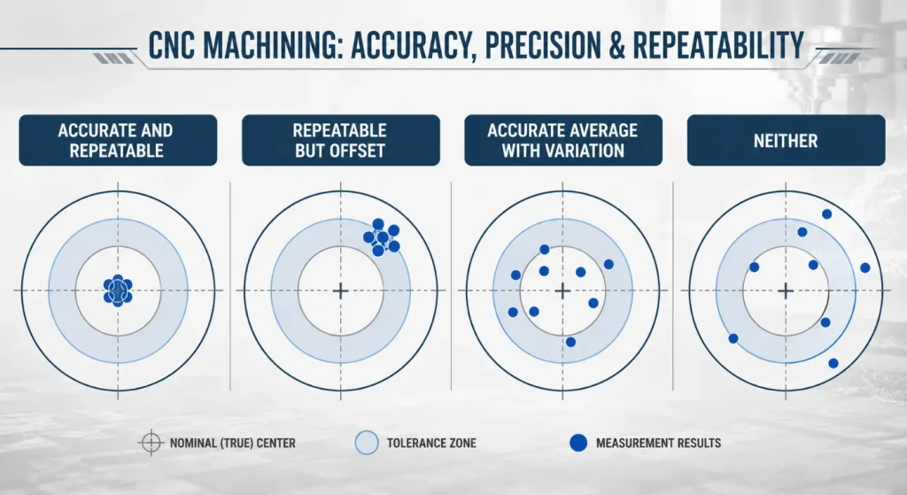
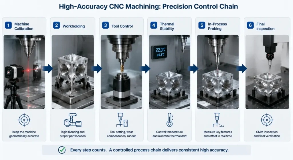
The machine, fixture, tool, program, environment, and inspection system must work as one process.
Start With Function, Not the Tightest Possible Tolerance
Applying tight tolerances to every drawing dimension rarely produces the best engineering or purchasing result.
It can increase:
- Programming time
- Fixture complexity
- Tooling requirements
- Machining cycles
- Scrap risk
- Inspection time
- Documentation cost
- Quotation uncertainty
Instead, the drawing should distinguish between general dimensions and critical-to-function features.
Common critical features include:
- Shaft and bearing fits
- Precision bores
- Sealing surfaces
- Hole patterns
- Mating faces
- Concentric diameters
- Gear or pulley locations
- Flatness and parallelism
- Perpendicular mounting faces
- Profile-controlled surfaces
- Threads affecting assembly
- Features controlling runout
ISO 2768-1 provides general tolerance classes for certain linear and angular dimensions without individual tolerance indications. It is intended to simplify drawing indications, not to replace specific tolerances on functional features. (ISO 2768-1)
Use GD&T to Communicate Functional Relationships
A coordinate dimension alone may describe where one feature appears on a drawing, but it may not adequately communicate how the feature must relate to the rest of the part.
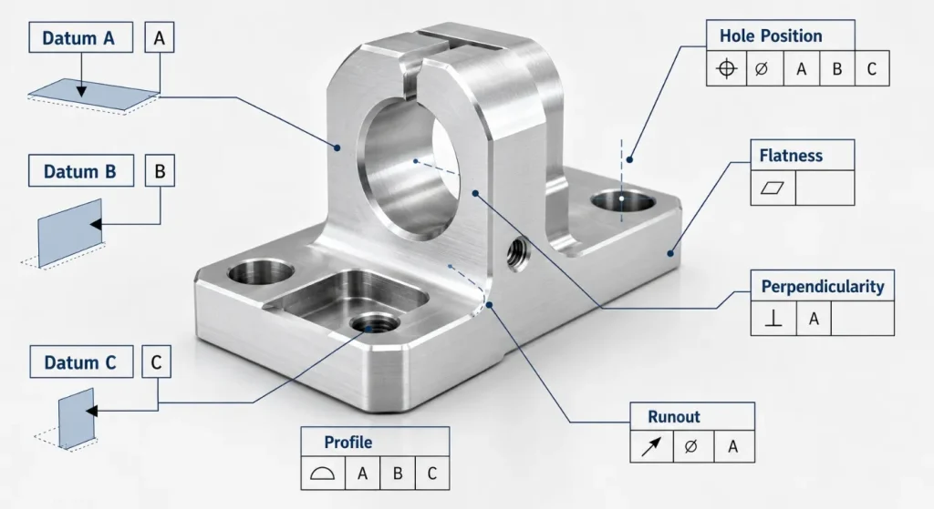
Geometric dimensioning and tolerancing can define:
- Form
- Orientation
- Position
- Profile
- Runout
- Datum relationships
ASME Y14.5 establishes standardized symbols and rules for communicating GD&T and design intent.
A useful datum system should reflect how the component is:
- Located in an assembly
- Supported during operation
- Machined
- Inspected
- Mated with adjacent parts
Datums should not be selected only because a surface is convenient for the supplier to probe or clamp.
When drawing intent is unclear, two manufacturers may produce parts that meet individual coordinate dimensions but behave differently during assembly.
What Controls CNC Machining Accuracy?
Machine Condition and Calibration
Machine axis positioning, rotary-axis behavior, spindle condition, geometric alignment, and compensation influence machining results.
ISO 230-2 specifies methods for evaluating the positioning accuracy and repeatability of numerically controlled machine-tool axes. (ISO 230-2)
Machine capability is important, but a machine specification alone does not guarantee a particular part tolerance. The result remains dependent on the complete manufacturing task.
Workholding and Datum Transfer
A fixture should locate the part repeatably without causing deformation.
Risks include:
- Thin-wall distortion
- Shaft bending
- Movement after unclamping
- Contamination under datum surfaces
- Excessive clamping force
- Datum changes between setups
- Inconsistent fixture loading
Reducing unnecessary re-clamping can help maintain relationships between features.
For parts combining diameters, bores, flats, slots, and cross holes, CNC turning and milling may help control features relative to a common datum.
Tool Condition and Cutting Strategy
Tool wear can gradually change:
- Bore diameter
- Slot width
- Surface finish
- Corner radius
- Thread quality
- Part position under cutting force
A high-accuracy process may require:
- Controlled tool life
- Tool offset management
- Roughing and finishing tools
- Stable engagement
- Suitable coolant delivery
- Tool-breakage detection
- In-process checks
Thermal Stability
Heat from the spindle, cutting process, coolant, machine structure, and workshop environment can affect dimensions.
Temperature becomes more important when:
- The part is large
- Tolerances are tight
- Different materials are involved
- Machining cycles are long
- Inspection occurs in another room
- The component has a high thermal-expansion coefficient
NIST has documented how temperature and material thermal-expansion behavior contribute to dimensional measurement uncertainty. (NIST dimensional measurement and temperature)
Parts may need to stabilize before final inspection rather than being measured immediately after machining.
Material Behavior
Different materials respond differently to machining and measurement.
- Aluminum: Can be sensitive to thin-wall distortion, residual stress, and clamping.
- Stainless steel: May generate cutting heat, form persistent burrs, and work-harden.
- Titanium: Requires heat and tool-wear control.
- Hardened steel: May need rigid setups, suitable tooling, grinding, or EDM.
- Copper: Can create chip-control and burr challenges.
- Engineering plastics: May deform under clamping or change dimension with temperature and moisture.
For material-specific planning, buyers can review SunOn’s stainless steel CNC machining guide and PEEK CNC machining guide.
Match the Process to the Geometry
CNC Milling
CNC milling suits:
- Housings
- Plates
- Brackets
- Pockets
- Slots
- Sealing faces
- Hole patterns
- Complex prismatic parts
Accuracy depends on tool access, fixture support, datum strategy, wall thickness, and setup sequence.
CNC Turning
CNC turning is typically used for:
- Shafts
- Pins
- Bushings
- Sleeves
- Fittings
- Nozzles
- Threaded components
Important controls may include:
- Outside and inside diameter
- Concentricity
- Circular runout
- Shoulder position
- Bore alignment
- Surface finish
Five-Axis CNC Machining
Five-axis CNC machining may reduce the need to reposition complex parts.
It can be useful for:
- Angled holes
- Multi-face features
- Compound surfaces
- Complex housings
- Aerospace-style brackets
- Datum-sensitive geometry
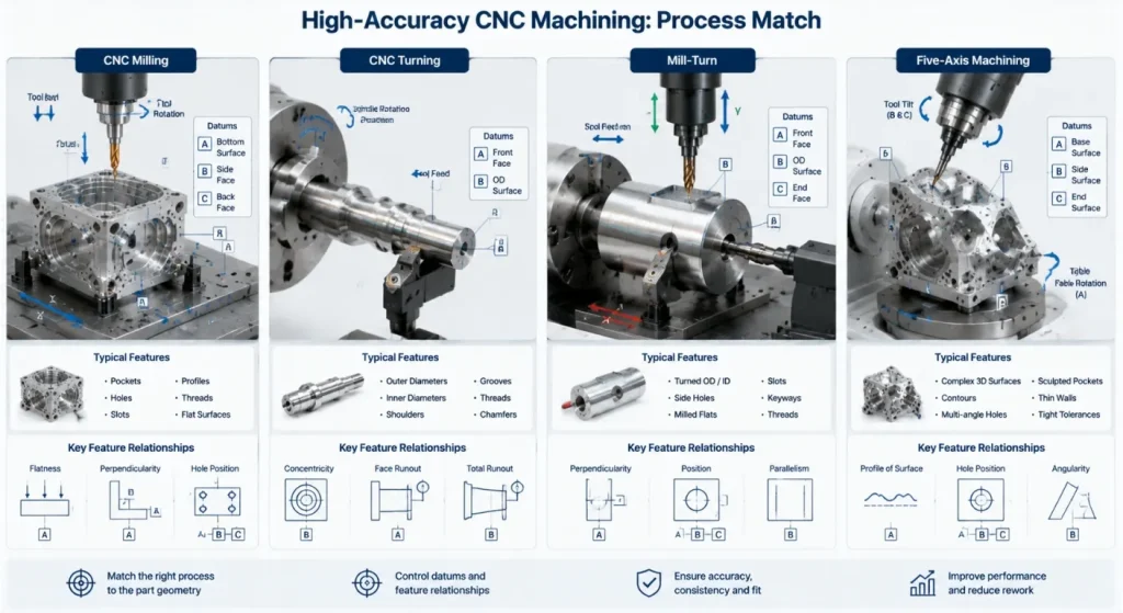
Five-axis machining is not automatically more accurate than every three-axis process. Its value depends on whether reduced setups improve access, alignment, and process stability for the specific part.
Common DFM Risks in High-Accuracy Parts
Thin Walls
Thin sections may move under cutting force, fixture pressure, residual stress, or heat.
Possible controls include:
- Increasing wall thickness
- Supporting the workpiece
- Balancing material removal
- Separating roughing and finishing
- Reducing clamping pressure
- Inspecting after release from the fixture
Long, Slender Features
Long shafts, pins, ribs, and unsupported walls may deflect during machining.
A part that can be modeled in CAD is not automatically rigid enough for the selected manufacturing process.
Deep Bores and Pockets
Deep features may require long tools and can increase vibration, heat, chip-evacuation difficulty, and inspection limitations.
Excessive Datum Transfers
Each setup can introduce additional variation. Features with close relationships should be evaluated for machining from a shared datum or in fewer controlled setups.
Tight Tolerances After Finishing
Anodizing, plating, heat treatment, polishing, coating, and passivation-related processing can influence final dimensions or surface condition.
The RFQ should state whether requirements apply:
- Before finishing
- After finishing
- At selected masked areas
- At final assembly condition
In-Process Control and Probing
Machine-tool probes can support:
- Automated workpiece setup
- Datum location
- Tool setting
- In-process gauging
- Offset correction
- Broken-tool detection
Renishaw describes machine-tool probing as a method for automated setup, in-cycle gauging, tool measurement, and process control. (Renishaw machine-tool probing)
On-machine measurement can help detect process drift, but it is not automatically an independent replacement for final inspection.
The same machine structure may influence both machining and on-machine measurement. Critical acceptance requirements may still need CMM, optical, gauge, roughness, or functional verification outside the machining process.
Inspection and Measurement Capability
A high-accuracy machining claim should be supported by an inspection method suitable for the feature.
Possible methods include:
- Micrometers
- Bore gauges
- Height gauges
- Thread gauges
- CMM
- Optical measurement
- Roundness measurement
- Surface-roughness testing
- Flatness inspection
- Functional gauges
- Assembly tests
Measurement uncertainty should be considered when tolerance limits are close to the capability of the inspection system. NIST defines measurement uncertainty as a parameter characterizing the dispersion of values that can reasonably be attributed to the quantity being measured. (NIST measurement uncertainty)
The inspection plan should define:
- Critical characteristics
- Measurement method
- Datum alignment
- Sampling or 100% inspection
- Inspection temperature
- Report format
- First-article requirements
- Traceability
- Acceptance decision rules
Standard CNC Machining vs. High-Accuracy CNC Machining
| Decision Factor | General CNC Machining | High-Accuracy CNC Machining |
|---|---|---|
| Drawing approach | General tolerances may dominate | Functional tolerances and GD&T are prioritized |
| Setup planning | Standard fixtures may be sufficient | Datum transfer and deformation require detailed review |
| Tool control | Routine replacement | Controlled offsets and tool-life monitoring |
| Thermal control | Normal workshop management | Part, machine, and inspection temperature may require review |
| In-process checks | Selected dimensions | Process-sensitive features may be monitored |
| Inspection | Manual gauges or sampling | CMM, optical, gauges, and formal reports may be combined |
| Documentation | Basic inspection records | FAI, ballooned drawing, dimensional report, or traceability |
| Cost driver | Machining time and material | Process stability, inspection, tooling, and documentation |
High-accuracy machining should be requested when the product function justifies the additional process and verification effort.
From Drawing Review to Verified Parts
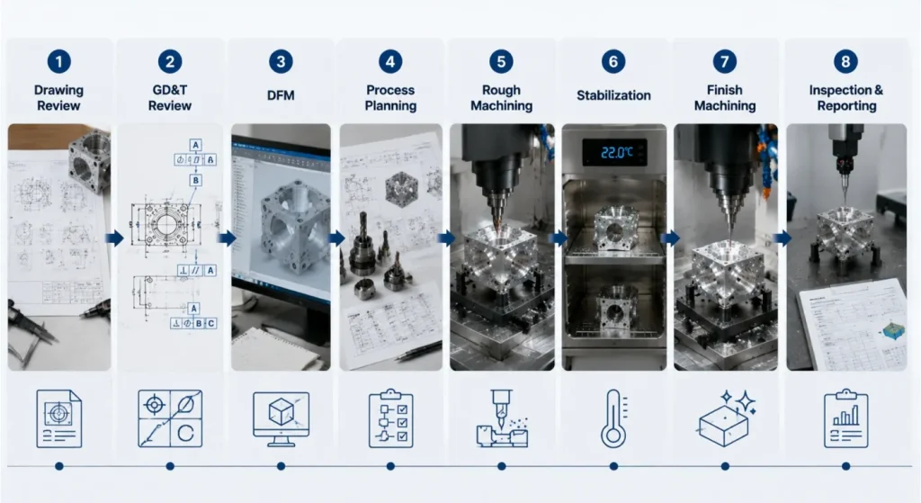
A controlled project commonly follows these stages:
- RFQ Review: Confirm material, quantity, tolerances, finish, documentation, and delivery.
- Drawing and GD&T Review: Identify functional datums and critical characteristics.
- DFM Review: Evaluate tool access, wall thickness, distortion, burrs, and inspection.
- Process Planning: Define machines, fixtures, setups, tools, and operation sequence.
- Rough Machining: Remove material while managing stress and deformation.
- Stabilization: Allow temperature or material condition to settle where required.
- Finish Machining: Complete critical dimensions and functional surfaces.
- Inspection: Verify the agreed characteristics with suitable measurement tools.
- Reporting and Packaging: Supply required records and protect functional surfaces.
What to Include in a High-Accuracy CNC Machining RFQ
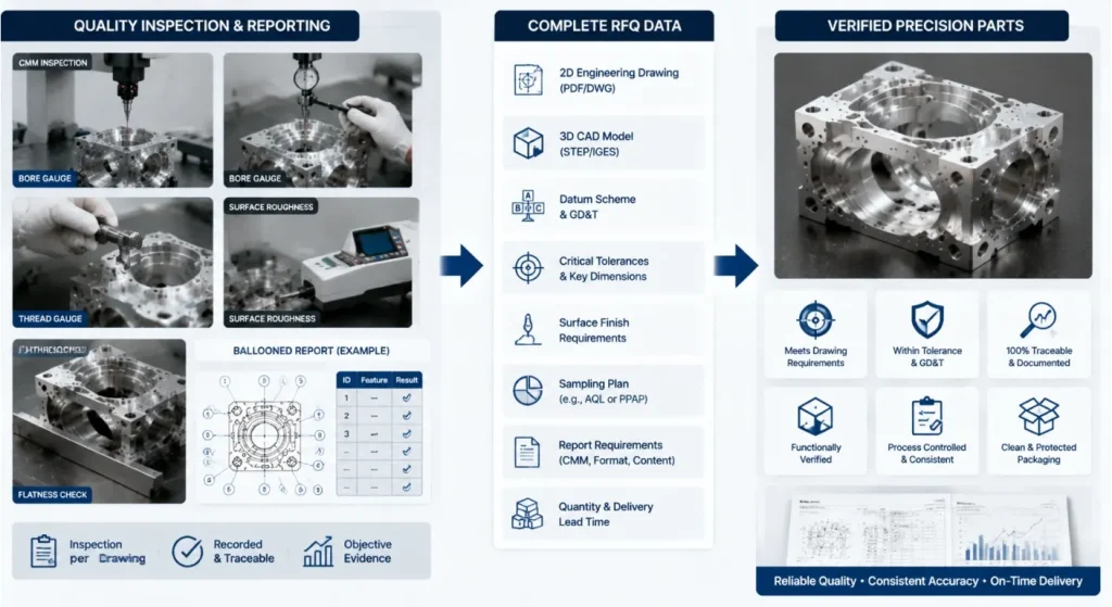
Provide:
- Controlled 2D engineering drawing
- 3D CAD model
- Drawing revision
- Material grade and condition
- Prototype and production quantities
- Functional datum system
- Critical dimensions and GD&T
- Fits and mating requirements
- Surface-roughness requirements
- Threads and inserts
- Heat treatment and surface finishing
- Dimensions applying after finishing
- First-article requirements
- Sampling or 100% inspection
- Inspection-report format
- Material and process certificates
- Packaging and delivery requirements
SunOn’s CNC machining quotation guide provides additional guidance for preparing project files.
Frequently Asked Questions
1. What Tolerance Defines High-Accuracy CNC Machining?
There is no universal tolerance that defines every high-accuracy project. Capability depends on material, part size, geometry, setup, thermal conditions, surface finish, and inspection method.
2. Is Machine Accuracy the Same as Finished-Part Accuracy?
No. Machine positioning capability is only one contributor. Fixtures, tools, cutting forces, material behavior, temperature, setups, finishing, and measurement also affect the finished part.
3. Should Every Drawing Dimension Have a Tight Tolerance?
No. Tight tolerances should be limited to features affecting fit, sealing, alignment, motion, load transfer, or interchangeability. Applying them to non-critical dimensions increases cost without necessarily improving performance.
4. Does Five-Axis Machining Always Produce More Accurate Parts?
Not automatically. Five-axis machining can improve access and reduce re-clamping, which may help control related features, but accuracy still depends on calibration, fixtures, tooling, geometry, and inspection.
5. How Are High-Accuracy CNC Parts Inspected?
Inspection may combine CMM, micrometers, bore gauges, thread gauges, optical measurement, roughness testing, and functional gauges. The correct method depends on the feature, tolerance, accessibility, and reporting requirement.
6. What Information Is Needed for an Accurate CNC Machining Quote?
Provide controlled 2D and 3D files, material, quantity, datums, critical tolerances, GD&T, finish, heat treatment, and inspection requirements. Clearly identify which dimensions apply after secondary processing.
Conclusion
High-accuracy CNC machining is not defined by one machine, one tolerance, or one inspection certificate.
Reliable results come from connecting product function with material selection, datum planning, setup control, cutting strategy, thermal management, tool monitoring, surface finishing, and suitable inspection.
The drawing should identify the features that truly control fit, sealing, alignment, motion, or interchangeability. General dimensions should not be tightened without a functional reason.
To request a manufacturability and tolerance review, contact SunOn with your 2D drawing, 3D CAD model, material, quantities, critical characteristics, finish, and inspection requirements.
