


LED Lighting Die Casting: Housing, Thermal, Sealing, and RFQ Guide
LED lighting die casting produces custom metal housings, heat sinks, driver enclosures, mounting structures, and sealed luminaire bodies for indoor and outdoor lighting products.
Unlike a general decorative enclosure, a die-cast LED lighting component may perform several functions at once. It can transfer heat away from the LED board, locate the optical system, protect the driver, support a gasket, provide mounting strength, establish electrical grounding, and resist outdoor exposure.
For lighting engineers and technical buyers, the central question is therefore not simply whether an aluminum housing can be die cast. It is whether the complete housing can control temperature, maintain optical and sealing interfaces, withstand installation loads, support finishing, and remain repeatable in production.
SunOn supports custom aluminum die casting parts from luminaire housing review and mold engineering through casting, CNC machining, coating, inspection, and repeat production.
LED Lighting Die Casting at a Glance
| Lighting Requirement | Main Die Casting Consideration |
|---|---|
| High-power LED module | Create a controlled thermal path from PCB to housing |
| Outdoor luminaire | Coordinate enclosure, gasket, fasteners, cable entry, and drainage |
| Street or tunnel light | Review wind load, mounting strength, corrosion, and heat dissipation |
| Floodlight or high-bay fixture | Control heat-sink area, weight, bracket loads, and driver temperature |
| Optical lens or reflector | Maintain locating surfaces and screw positions |
| Integrated driver compartment | Separate thermal zones and protect electronic components |
| Powder-coated exterior | Define pretreatment, masking, thickness, and cosmetic zones |
| Precision LED-board interface | Add machining allowance and flatness requirements |
| Formal IP requirement | Test the assembled luminaire, not only the casting |
| Long-term production | Define mold maintenance, process control, coating, and traceability |
What LED Lighting Parts Are Commonly Die Cast?
Die casting is commonly considered for lighting components that require complex geometry, integrated ribs, mounting features, heat-dissipation surfaces, and repeat production.
Typical parts include:
- Street-light housings
- Floodlight bodies
- High-bay lighting housings
- Tunnel-light housings
- Wall-pack enclosures
- Canopy-light bodies
- Landscape-light housings
- Driver compartments
- LED module bases
- Heat-sink structures
- Mounting arms and brackets
- End caps and junction housings
Some luminaires use one integrated die casting, while others divide the product into a heat sink, driver box, optical frame, mounting bracket, and cover.
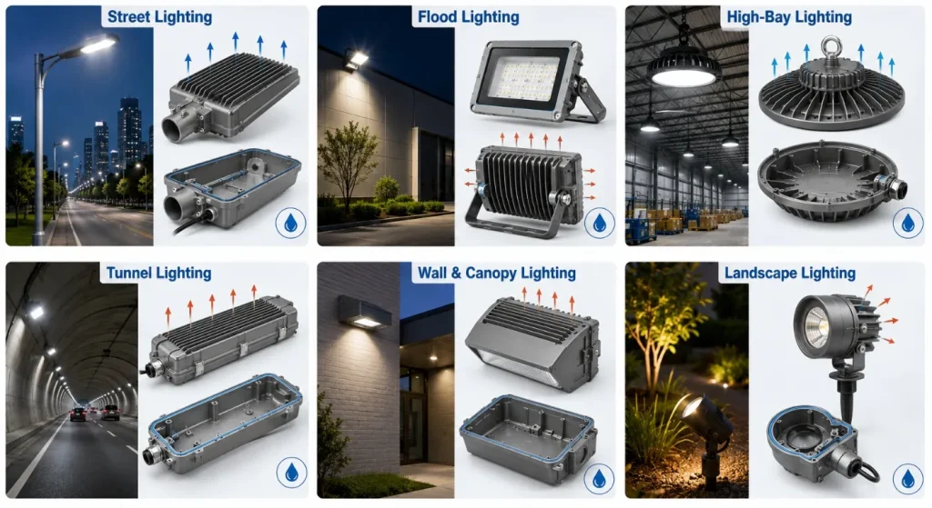
The correct architecture depends on thermal load, size, service access, sealing, tooling cost, product family, and assembly strategy.
Treat the Housing as Part of the Thermal System
LED products convert part of their electrical input into heat. ENERGY STAR explains that the heat produced by LEDs is absorbed into a heat sink to reduce performance problems.
A typical thermal path may be:
LED Junction → LED Package → PCB or MCPCB → Thermal Interface → Die-Cast Housing → Fins and External Air
Every interface adds thermal resistance.
The die-cast housing should therefore be developed together with:
- LED package and board
- Board material and thickness
- Thermal-interface material
- Contact area
- Fastener pattern
- Housing base thickness
- External fins
- Airflow orientation
- Driver location
- Ambient temperature
A large housing is not automatically a good heat sink. Poor contact flatness, isolated heavy sections, ineffective fins, trapped air, coating on a thermal interface, or inadequate airflow can reduce thermal performance.
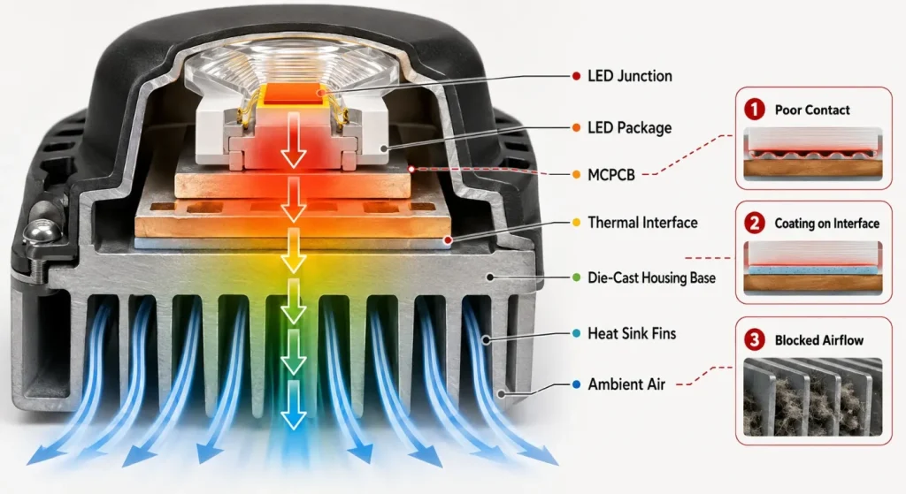
SunOn’s die-cast heat sink guide provides additional information on integrating casting geometry with thermal-management components.
Design a Continuous Thermal Path
LED Board Contact Surface
The LED-board mounting surface should provide stable contact with the PCB or thermal-interface material.
Important requirements may include:
- Flatness
- Surface roughness
- Board support
- Fastener spacing
- Thermal-interface thickness
- Machining condition
- Cleanliness
- Coating or masking condition
A rough or distorted casting surface may create uneven contact. Selected LED-board interfaces may therefore require CNC face milling.
Base Thickness
A base that is too thin may not spread heat effectively or may distort during casting and assembly. A base that is unnecessarily thick adds weight, material, thermal mass, and cooling time.
The thickness should be determined through thermal and structural analysis rather than copied from an unrelated luminaire.
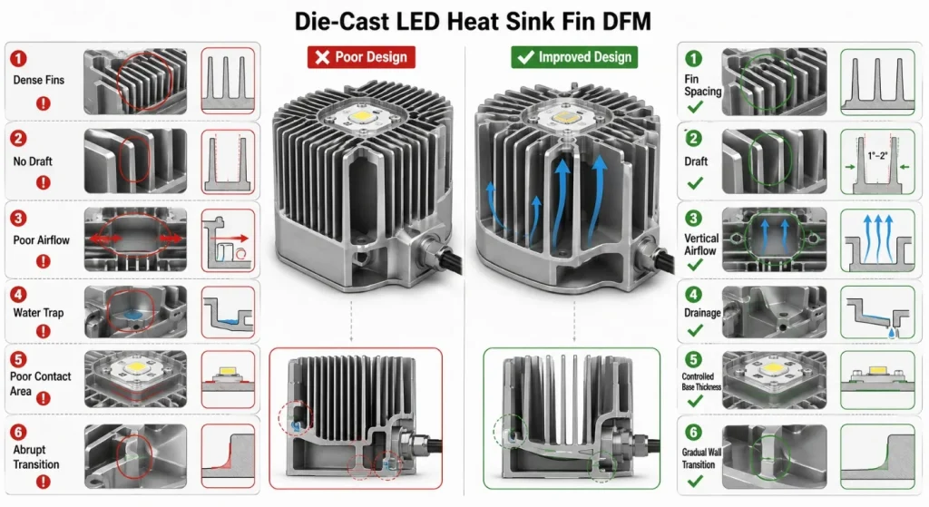
Fin Geometry
Heat-sink fins should be designed around the actual airflow and casting direction.
Fin design may involve:
- Height
- Thickness
- Spacing
- Draft
- Orientation
- Connection radius
- Dirt accumulation
- Water drainage
- Tooling access
- Ejection
Closely spaced fins increase nominal surface area but may restrict natural airflow, retain dust, complicate coating, or create difficult die-casting conditions.
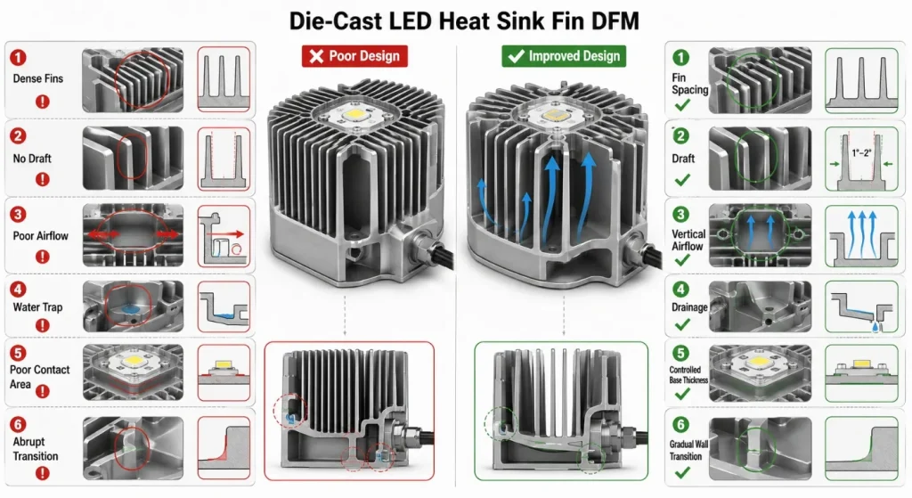
For outdoor luminaires, fin direction should also avoid creating water traps.
Coordinate Thermal and Driver Compartments
The LED module and electronic driver do not always benefit from the same enclosure arrangement.
An integrated housing can reduce part count, but heat from the LED section may raise the temperature around:
- Electrolytic capacitors
- Power electronics
- Wiring
- Connectors
- Surge-protection components
- Control modules
DOE solid-state-lighting research has identified thermal management as an important contributor to LED-system and driver reliability.
Possible design directions include:
- Separate LED and driver compartments
- Thermal barriers between zones
- External driver mounting
- Dedicated driver heat paths
- Ventilated non-sealed driver chambers
- Replaceable driver modules
- Independent service covers
The choice depends on luminaire power, environment, maintenance strategy, electronics, and target enclosure rating.
Design the Housing Around Optics and Light Control
A die-cast housing may locate:
- LED board
- Reflector
- TIR lens
- Diffuser
- Glass cover
- Optical frame
- Secondary lens array
Optical misalignment can affect beam distribution even when the casting meets its general external dimensions.
Critical optical features may include:
- LED-board position
- Lens-to-LED distance
- Reflector concentricity
- Optical-frame flatness
- Screw-hole position
- Cover compression
- Reference datums
These features should be identified on the engineering drawing and connected through a functional datum system.
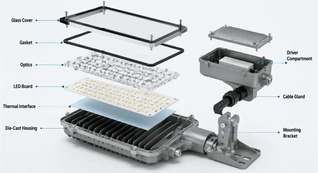
A cosmetic exterior dimension does not necessarily control the optical relationship inside the product.
Plan Sealing as a Complete Enclosure System
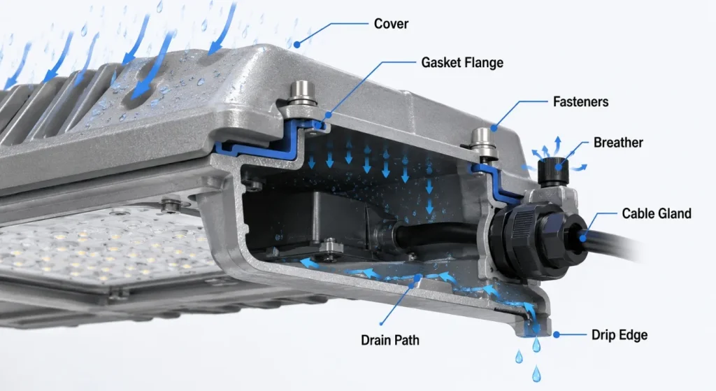
IEC 60529 classifies the degree of protection provided by electrical enclosures against solid objects and water. The IP rating applies to the completed enclosure configuration, not to an individual metal casting.
An outdoor LED housing should be reviewed together with:
- Cover or lens
- Gasket
- Fasteners
- Cable glands
- Connectors
- Breather or vent
- Drainage features
- Casting porosity
- Machined sealing surfaces
- Coating
- Assembly torque
Gasket Flange
The gasket flange should provide:
- Continuous sealing geometry
- Controlled flatness
- Suitable gasket width
- Fastener support
- Corner radii compatible with the seal
- No gate or ejector interference
- No coating buildup that changes compression unexpectedly
Water Management
Avoiding water entry is important, but designers should also plan what happens to condensation or incidental moisture.
Possible features include:
- Sloped exterior surfaces
- Drain paths
- Drip edges
- Protected breather locations
- Downward-facing cable entries
- Separated wet and electrical zones
A nominally sealed housing can still experience internal moisture due to temperature and pressure changes.
Select the Alloy and Casting Process
Aluminum die casting is commonly used for LED housings because it can integrate heat-sink fins, mounting bosses, sealed compartments, brackets, and optical interfaces.
The exact alloy should be selected according to:
- Castability
- Thermal performance
- Corrosion exposure
- Mechanical strength
- Surface finishing
- Machining
- Wall and fin geometry
- Production equipment
- Customer specification
A general-purpose aluminum die casting alloy may suit many commercial luminaires. Applications prioritizing thermal conductivity, structural performance, pressure integrity, or corrosion behavior may require a more specialized grade and process.
The RFQ should identify the exact alloy standard rather than using only “die-cast aluminum.”
Design for Mold Filling and Ejection
LED lighting housings often combine:
- Broad thin walls
- Deep external fins
- Driver cavities
- Mounting bosses
- Sealing flanges
- Cable-entry features
- Decorative surfaces
These features can create long flow paths and uneven thermal mass.
Design review should address:
- Controlled wall transitions
- Fin draft
- Boss coring
- Fillet radii
- Gate location
- Vent and overflow locations
- Ejector positions
- Parting-line position
- Slider requirements
- Machining allowance
Visible surfaces should be identified before mold design so gates, flash, ejector marks, and overflow removal do not damage the final appearance.
Detailed tooling requirements are discussed in SunOn’s die casting mold design guide.
Secondary CNC Machining
Selected LED housing features may require machining after casting.
Common operations include:
- LED-board mounting-face milling
- Lens or glass seating-face machining
- Gasket-flange machining
- Connector-hole drilling
- Cable-entry tapping
- Mounting-hole machining
- Grounding-pad preparation
- Thread tapping
- Bracket-interface machining
The design should define:
- As-cast datums
- Machining datums
- Machining allowance
- Final flatness
- Surface roughness
- Burr requirements
- Coating mask areas
SunOn’s secondary machining for aluminum die castings explains why machining allowance and feature planning should begin before mold manufacture.
Surface Treatment and Corrosion Protection
LED lighting housings may receive:
- Shot blasting
- Bead blasting
- Chemical conversion treatment
- Powder coating
- Wet painting
- Plating
- Local masking
- Laser marking
Outdoor products should coordinate coating with:
- UV exposure
- Humidity
- Rain
- Road salt or coastal exposure
- Cleaning chemicals
- Fasteners
- Grounding points
- Thermal interfaces
- Gasket surfaces
ISO 9227 describes salt-spray test methods but does not prescribe the correct exposure period or pass criteria for a specific product. Those requirements must come from the applicable product or customer specification.
A salt-spray duration should therefore not be quoted as a universal indicator of field life.
For broader coating considerations, review SunOn’s corrosion-resistant aluminum die casting guide.
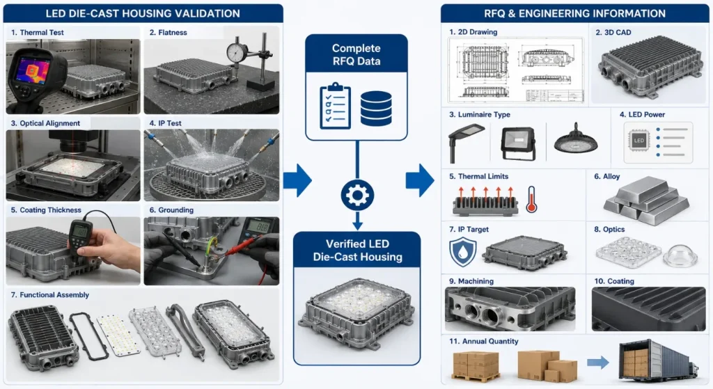
Validate More Than Casting Dimensions
LED lighting validation may include:
- Alloy verification
- Casting dimensional inspection
- CMM inspection
- LED-board interface flatness
- Optical alignment
- Thread and connector checks
- Coating thickness
- Coating adhesion
- Grounding continuity
- Thermal testing
- Ingress-protection testing
- Functional lighting tests
- Assembly and torque verification
- Packaging inspection
IES explains that LM-80 and TM-21 support evaluation and projection of LED-source lumen maintenance, but the complete luminaire has additional failure mechanisms involving drivers, optics, thermal management, and other components.
The casting supplier should therefore avoid claiming a complete luminaire lifetime based only on the housing material or LED package data.
Die Casting vs. Other Housing Processes
| Process | Often Suitable For | Main Limitation to Review |
|---|---|---|
| Aluminum die casting | Integrated housings, fins, bosses, compartments, repeat production | Tooling investment and casting DFM |
| Aluminum extrusion | Linear heat sinks and constant cross-sections | Limited three-dimensional geometry |
| Sheet metal | Large covers, simple driver boxes, lower tooling investment | Joining, sealing, stiffness, and thermal interfaces |
| CNC machining | Prototypes and low-volume precision housings | Material waste and unit cost |
| Injection-molded plastic | Insulated covers and low-load enclosures | Thermal transfer, grounding, shielding, and temperature |
| Hybrid construction | Products combining casting, extrusion, sheet, glass, and plastic | Assembly, sealing, tolerance stack, and supply-chain complexity |
The most suitable luminaire may combine a die-cast heat sink, extruded rail, sheet-metal driver box, glass cover, molded optical component, and silicone gasket.
From Luminaire Review to Production
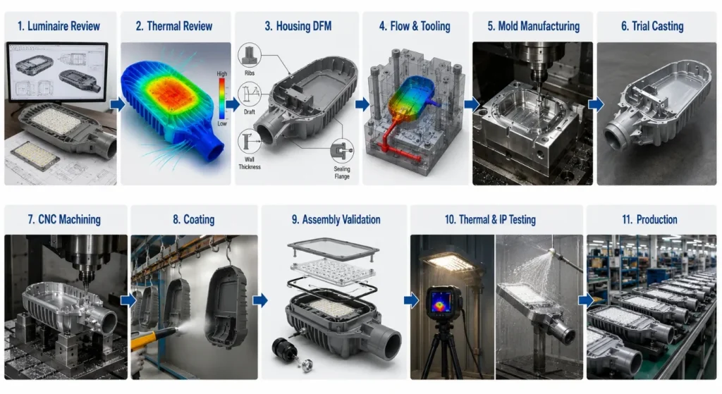
A controlled LED lighting die casting project commonly follows:
- Luminaire Review: Confirm lighting type, power, environment, optics, mounting, and product architecture.
- Thermal Review: Define LED, board, thermal-interface, housing, fin, and driver temperature requirements.
- Housing DFM: Review walls, fins, bosses, draft, seals, optics, and machining.
- Flow and Tooling Review: Plan gates, vents, overflows, cooling, slides, and ejection.
- Mold Manufacturing: Produce, heat treat, finish, and assemble the die.
- Trial Casting: Evaluate filling, fins, surfaces, dimensions, and ejection.
- CNC Machining: Complete thermal, sealing, optical, grounding, and mounting interfaces.
- Surface Treatment: Apply pretreatment, coating, masking, and marking.
- Assembly Validation: Install boards, optics, gaskets, covers, connectors, and fasteners.
- Testing: Complete thermal, ingress, electrical, optical, coating, and functional checks.
- Repeat Production: Maintain process, coating, inspection, traceability, and packaging controls.
For early designs, low-volume aluminum die casting or CNC-machined prototypes may support thermal and assembly validation before production tooling.
What to Include in an LED Lighting Die Casting RFQ
Provide:
- Controlled 2D drawing
- 3D CAD model
- Luminaire type and installation environment
- LED-board and driver arrangement
- Power and thermal requirements
- Required aluminum alloy
- Annual and lifetime quantities
- Critical optical datums
- LED-board contact requirements
- Fin and airflow direction
- Gasket and enclosure interfaces
- Required IP classification
- Cable entries and connectors
- Grounding requirements
- Machined features
- Coating and cosmetic zones
- Corrosion-test requirements
- Thermal and functional tests
- Packaging and delivery requirements
Conclusion
Reliable LED lighting die casting begins with the complete luminaire system rather than the external shape of the housing.
The casting may need to transfer LED heat, protect the driver, locate optics, support sealing, provide grounding, resist installation loads, accept coating, and remain serviceable throughout the product’s intended use.
Thermal paths, fin geometry, wall design, optical datums, gaskets, cable entries, machining, corrosion protection, and validation should be planned together.
Die casting creates the most value when it integrates these functions without introducing unnecessary weight, trapped heat, water paths, coating problems, or assembly complexity.
To request an LED lighting housing review, contact SunOn with the luminaire files, thermal requirements, alloy, quantity, sealing, optics, machining, coating, testing, and packaging requirements.
Frequently Asked Questions About LED Lighting Die Casting
1. Why Is Aluminum Die Casting Used for LED Lighting Housings?
Aluminum die casting can integrate heat-sink fins, mounting bosses, driver compartments, sealing flanges, and optical supports in one part. Its suitability still depends on thermal load, quantity, geometry, coating, and tooling investment.
2. Does a Larger Die-Cast Housing Always Provide Better Cooling?
No. Cooling depends on the complete thermal path, contact flatness, base thickness, fin geometry, airflow, coating, ambient conditions, and driver arrangement. Additional metal can increase weight without improving effective heat transfer.
3. Can a Die-Cast Housing Guarantee an IP Rating?
No. An IP rating applies to the assembled enclosure, including the housing, cover, gasket, fasteners, cable entries, connectors, vents, coating, and assembly process. The finished luminaire must be tested in its production configuration.
4. Which LED Housing Surfaces Usually Require CNC Machining?
Common machined areas include LED-board interfaces, gasket flanges, lens seats, connector holes, cable entries, grounding pads, and mounting interfaces. Machining should be limited to features that require controlled flatness, position, threads, or sealing.
5. Which Finish Is Suitable for Outdoor LED Housings?
Powder coating and other protective systems may be suitable depending on the alloy, pretreatment, UV exposure, humidity, salt, temperature, and cosmetic requirements. Thermal interfaces, grounding pads, threads, and gasket surfaces may require masking.
6. What Information Is Needed for an LED Lighting Die Casting Quote?
Provide the housing drawings, luminaire type, LED and driver arrangement, power and thermal requirements, alloy, quantities, optical datums, sealing, IP target, machining, coating, tests, and packaging requirements.
