
How to Achieve Smooth Surface Finish in 3D Printing (Ra 0.5 µm)
Achieving a surface roughness of Ra 0.5 µm in 3D printing represents the transition from a "prototype look" to a "production-grade finish." In industrial manufacturing, an Ra 0.5 µm finish is comparable to a fine-ground or polished surface, where layer lines are invisible to the naked eye and barely detectable by touch. For B2B buyers in the medical, automotive, and electronics sectors, this level of smoothness is often a functional requirement for parts that must be airtight, biocompatible, or aesthetically flawless.
Understanding Surface Roughness (Ra) in Additive Manufacturing
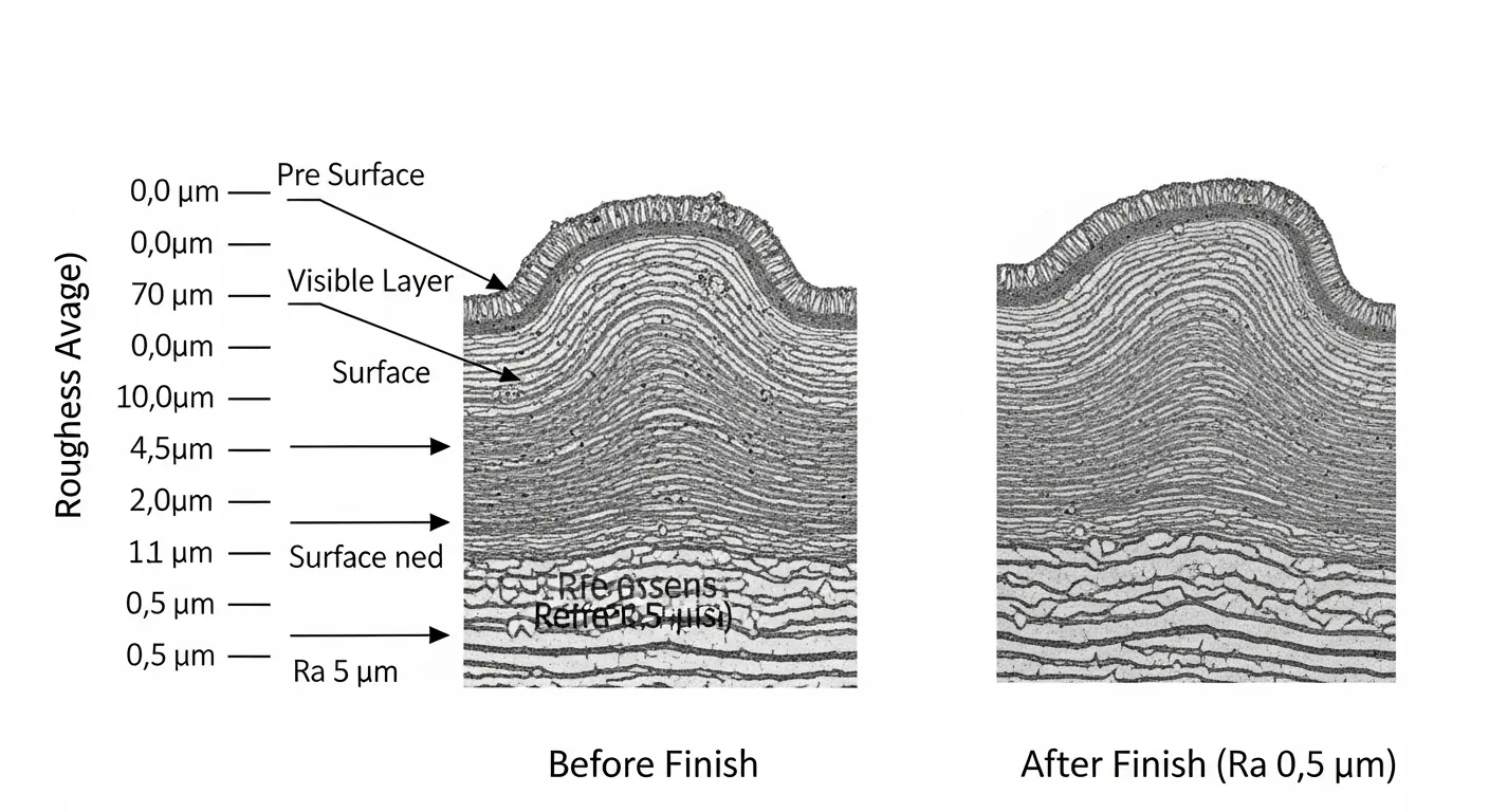
Surface roughness is measured using the Ra (Roughness Average) scale, which calculates the arithmetic average of the profile height deviations from the mean line. Most raw 3D prints emerge with an Ra between 12.5 µm and 25 µm (FDM) or 3.2 µm and 6.3 µm (SLA/SLS).
To move from these raw states to a high-precision Ra 0.5 µm, a combination of hardware optimization and secondary post-processing is required. Achieving this target is not just about aesthetics; it significantly reduces friction in mechanical assemblies and prevents bacterial growth in medical models by eliminating the microscopic "valleys" where contaminants can hide.
Step 1: Hardware and Process Optimization
The journey to a smooth finish begins before the machine starts. While post-processing does the heavy lifting, the "near-net-shape" quality of the print dictates how much labor is required later.
1. Technology Selection
Not all 3D printing technologies are equal when it comes to smoothness. To hit Ra 0.5 µm, liquid-based systems are preferred:
- SLA (Stereolithography): Offers the best baseline. Its use of liquid resin and laser curing results in a nearly isotropic part with the lowest initial Ra.
- DLP (Digital Light Processing): Similar to SLA, but requires careful anti-aliasing settings to prevent "pixelation" on curved surfaces.
- PolyJet: Capable of high resolution, but often requires significant cleaning of support material which can affect the local Ra.
2. Layer Height and Orientation
Reducing layer height (e.g., to 25 or 50 microns) minimizes the "stair-stepping" effect. However, orientation is more critical. Parts should be oriented so that critical surfaces are either vertical or at an angle that avoids shallow slopes, as horizontal "top" surfaces often exhibit the highest roughness due to layer transitions.
Step 2: Mechanical Post-Processing Techniques
Mechanical finishing is the most common way to reach Ra 0.5 µm. This involves the physical removal of material to level the peaks of the layer lines.
1. Multi-Stage Abrasive Sanding
This is the baseline for high-precision finishes. The process must be incremental:
- Start with 400-grit to remove support scars and major layer lines.
- Progress to 600, 800, and 1200-grit wet sanding.
- The final stage for Ra 0.5 µm typically requires 2000-grit or higher fine-polishing papers.
2. Centrifugal Barrel Finishing (Mass Finishing)
For batches of small parts, manual sanding is inefficient. Centrifugal finishing uses a drum filled with abrasive media (ceramic, plastic, or corn cob). The high-speed rotation creates intense pressure and friction, "scrubbing" the parts to a uniform finish. This is the preferred method for 3D-printed prototypes for consumer electronics that require a consistent tactile feel across 50+ units.
Step 3: Chemical and Vapor Smoothing
Chemical smoothing is a "non-contact" method that is highly effective for complex geometries where manual sanding cannot reach.
1. Vapor Smoothing (Vapor Polishing)
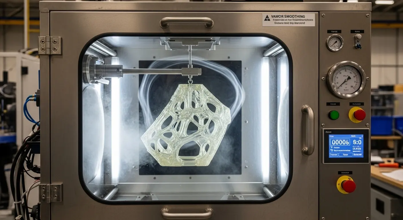
This involves exposing the part to a vaporized solvent (such as acetone for ABS or specialized chemicals for Nylon). The vapor partially melts the outer "skin" of the part, allowing surface tension to pull the material into a smooth, glossy state.
- Advantage: Reaches internal channels and intricate lattice structures.
- Result: Can consistently achieve Ra values below 1.0 µm, often hitting the 0.5 µm mark with industrial-grade vapor chambers.
2. Solvent Dipping
A more aggressive version of vapor smoothing where the part is briefly submerged in a solvent. This is difficult to control and can lead to a loss of dimensional accuracy, making it less suitable for high-precision 3D printing where ±0.1mm tolerances must be maintained.
Step 4: Secondary Machining (Hybrid Manufacturing)
When Ra 0.5 µm is required on specific functional features—like a bearing seat or an airtight seal—the best approach is CNC Finishing.
By 3D printing the part with a slight "offset" (extra material) and then using a CNC mill to shave off the final 0.2mm, you combine the geometric freedom of 3D printing with the precision finish of machining. This hybrid method is the standard for 3D-printed prototype for automotive components that require metal-to-plastic precision fits.
Quality Assurance: Verifying the Ra 0.5 µm Target
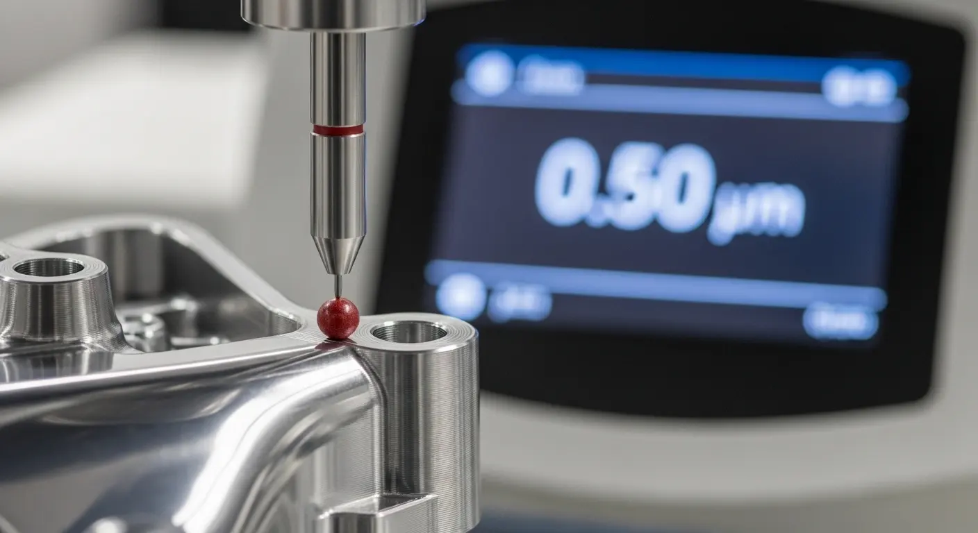
At SunOn, we do not guess the surface finish; we verify it. Achieving a verified Ra 0.5 µm requires professional metrology:
- Profilometers: A diamond-tipped stylus is dragged across the surface to map the peaks and valleys.
- Optical Gloss Meters: For clear or polished parts, light reflection is measured to ensure aesthetic consistency.
- CMM Inspection: To ensure that the material removed during polishing hasn't pulled the part out of its tolerance window.
Summary Table: Path to Ra 0.5 µm
| Technology | Raw Ra (Typical) | Finishing Method | Final Ra (Target) |
| SLA Resin | 3.2 µm | Wet Sand (2000 grit) + Buffing | 0.4 - 0.6 µm |
| MJF/SLS Nylon | 6.3 - 12.5 µm | Vapor Smoothing + Bead Blasting | 0.8 - 1.2 µm |
| FDM (ABS/ASA) | 15 - 25 µm | Acetone Vapor Polishing | 0.5 - 0.9 µm |
| Metal (DMLS) | 10 - 15 µm | CNC Machining / Electro-polishing | 0.2 - 0.5 µm |
Conclusion: Bridging Prototyping and Production
Hitting the Ra 0.5 µm benchmark is what transforms a 3D print into a production-ready component. Whether you are developing a medical device prototype 3D printing project that requires a low-friction surface or an automotive part that needs a Class-A finish, the secret lies in the synergy between the right technology and expert post-processing.
SunOn Industrial Group specializes in this high-end finishing. Our DFM-led approach ensures that your parts are designed with the final finish in mind, reducing labor costs and ensuring that your prototype-to-production journey is seamless.
Need a verified Ra 0.5 µm finish for your next project? Contact the SunOn engineering team today for a comprehensive DFM review and a quote for high-precision finishing.