


Cooling Channel Heat Sinks: Custom Manufacturing Options from SunOn
SunOn manufactures custom cooling channel heat sink components based on customer drawings, thermal requirements, and liquid-loop conditions. Unlike a conventional finned heat sink that transfers heat into surrounding air, this liquid-cooled design moves coolant through internal channels positioned close to the heat source.
Customers can specify the body dimensions, channel routing, inlet and outlet locations, mounting holes, threaded ports, heat-transfer surfaces, materials, finishes, and inspection requirements. SunOn supports drawing review, DFM, CNC machining, secondary processing, dimensional inspection, and production planning.
Send your 2D drawings or 3D models together with the coolant, flow rate, pressure, heat-load, and quantity requirements for a project-specific manufacturing review.
Custom Cooling Channel Heat Sinks Manufactured to Your Design
A cooling channel heat sink is not usually selected from a fixed catalogue. Its dimensions and internal flow path must match the heat source, available installation space, coolant circuit, mounting structure, and required thermal contact area.
SunOn can review custom designs for prototypes, pilot quantities, and repeat production. Depending on the approved design and manufacturing route, customizable features may include:
- Overall length, width, and thickness
- Internal channel path and cross-section
- Channel position relative to the heat source
- Heat-transfer contact area
- Inlet and outlet positions
- Port orientation and thread specifications
- Mounting holes, bosses, pockets, and alignment features
- O-ring, gasket, or other sealing interfaces
- Base flatness and surface finish
- External structural or heat-dissipation features
- Material and surface treatment
- Critical tolerances and inspection requirements
The final manufacturing approach depends on channel access, wall thickness, material, sealing requirements, operating pressure, quantity, and part geometry. These details should be reviewed before production rather than treated as fixed specifications.
When a Cooling Channel Heat Sink Fits Better Than an Air-Cooled Heat Sink
A cooling channel heat sink is typically considered when airflow alone cannot remove enough heat within the available space. It may also suit products that already use a pumped liquid loop or require more direct heat removal from concentrated heat sources.
Typical selection conditions include:
- High heat density
- Limited space for large fins
- Restricted or inconsistent airflow
- Multiple heat sources across one mounting surface
- A need to move heat into an external liquid circuit
- Noise limits that make large fans less desirable
- Integration of cooling, mounting, and fluid-routing features into one component
For a wider overview of conventional fin types and heat-sink construction methods, see heat sink types and manufacturing methods.
| Decision Factor | Cooling Channel Heat Sink | Conventional Air-Cooled Heat Sink |
|---|---|---|
| Cooling medium | Pumped liquid | Natural or forced air |
| Main geometry | Internal coolant passages | External fins or pins |
| System requirements | Pump, tubing, fittings, and heat rejection equipment | Airflow path and sometimes a fan |
| Typical fit | High heat density or restricted airflow | Moderate heat loads with sufficient airflow |
| Main design concerns | Flow rate, pressure drop, sealing, and fluid compatibility | Fin spacing, airflow, fan pressure, and available volume |
| Manufacturing focus | Channels, ports, enclosure, and leakage control | Fins, base geometry, casting, extrusion, or machining |
For projects where external fins and high-volume casting remain more practical, SunOn also offers aluminum die cast heat sinks.
Cooling Channel Design and Customization Options
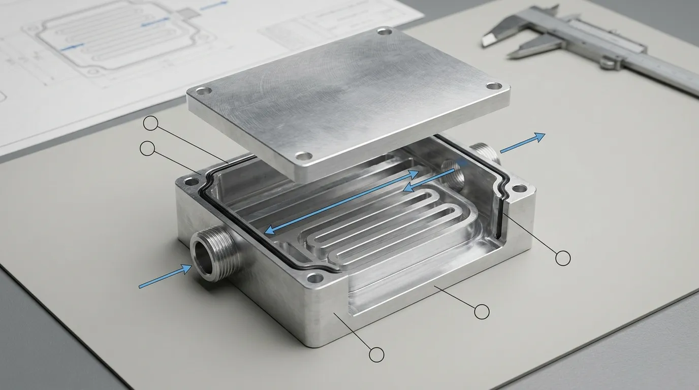
Channel Routing
The internal flow path should follow the heat-source arrangement instead of using a generic pattern without thermal or hydraulic justification. Depending on the part geometry, a design may use straight, serpentine, parallel, or application-specific channels.
The channel position, width, depth, spacing, and wall thickness influence both heat transfer and manufacturability. Sharp direction changes, inaccessible cavities, very thin walls, and unnecessarily complex paths can increase machining difficulty or create hydraulic restrictions.
Channel dimensions should therefore be finalized through DFM and system-level review rather than copied from another product.
Channel Size, Flow Rate, and Pressure Drop
Smaller or more restrictive passages may increase coolant velocity near the heat-transfer surface, but they can also create excessive pressure drop. The design must work with the pump, tubing, manifold, fittings, and other components in the full liquid loop.
For a useful review, the buyer should provide:
- Required flow rate
- Maximum allowable pressure drop
- Coolant type
- Coolant inlet temperature
- Maximum working pressure
- Target surface or component temperature
SunOn can then review whether the proposed geometry is practical to machine. Any thermal or hydraulic performance target should be validated using agreed engineering data and test conditions.
Inlet, Outlet, and Fitting Interfaces
Port design affects both coolant distribution and final assembly. The drawing should define:
- Inlet and outlet locations
- Port orientation
- Thread standard
- Fitting type
- Tube or hose direction
- Required tool clearance
- Connection to a wider cooling circuit
Where one coolant source must supply several components, a separate custom liquid cooling manifold may be used to distribute and collect flow.
Mounting and Thermal-Contact Surfaces
The heat-transfer surface must align with the heat source and provide reliable mechanical contact. Important drawing requirements include:
- Heat-source footprint
- Mounting-hole positions
- Base flatness
- Surface roughness
- Thermal interface material area
- Fastener locations
- Assembly pressure
- Component and fitting clearances
Projects with particularly demanding interface dimensions can also be reviewed alongside SunOn’s precision-machined cooling plates capabilities.
Materials and Surface Finishing
Aluminum is often a practical starting material for a custom cooling channel heat sink because it combines low weight, machinability, and useful thermal performance. The exact alloy should be selected according to machining requirements, strength, joining method, corrosion conditions, and compatibility with the coolant loop.
Copper may provide greater heat spreading but adds weight, material cost, and machining considerations. Hybrid aluminum-copper structures can balance performance and weight, but they also introduce joining and galvanic-corrosion concerns. Copper or hybrid production should only be specified after SunOn confirms the available manufacturing route.
| Material Direction | Main Benefit | Main Consideration |
|---|---|---|
| Aluminum body | Low weight and practical machinability | Alloy selection and coolant compatibility |
| Copper body | Greater heat spreading | Weight, cost, and machining requirements |
| Aluminum-copper hybrid | Performance and weight balance | Joining method and galvanic compatibility |
Related material-specific options are covered on SunOn’s custom aluminum cooling plates page.
Available surface conditions may include a machined finish or an approved secondary treatment. Anodizing, plating, bead blasting, brushing, or another finish should not automatically be applied to internal wetted surfaces. The selected coolant, base material, sealing method, and complete liquid loop must be considered first.
How SunOn Manufactures a Custom Cooling Channel Heat Sink
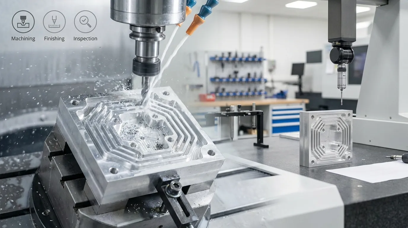
1. Drawing and Technical-Requirement Review
The process starts with the customer’s 2D drawing, 3D model, material specification, quantity, heat-source layout, coolant data, port requirements, tolerances, finish, and inspection expectations.
Missing information should be resolved before the part moves into production planning.
2. DFM and Manufacturing-Route Review
SunOn reviews factors such as:
- Channel accessibility
- Tool reach
- Channel depth
- Minimum wall thickness
- Port position
- Sealing surfaces
- Fixturing
- Critical tolerances
- Material availability
- Prototype and production quantities
CNC machining is often suitable for custom geometries, prototypes, and lower production volumes. Tooling-based manufacturing may become relevant for suitable high-volume components, although internal-channel construction must still be evaluated separately. SunOn’s heat sink die-casting mold development page provides additional context for dedicated tooling projects.
3. CNC Channel and Body Machining
The main body, internal channels, pockets, ports, grooves, threaded holes, mounting features, and thermal-contact surfaces can be produced through planned CNC operations.
The number of setups depends on the channel path, external geometry, access direction, and tolerance requirements. Projects focused specifically on machined liquid-cooling structures can also reference SunOn’s CNC-machined liquid cooling plates.
4. Channel Enclosure and Sealing
After machining, open channels must be enclosed using a method suitable for the material, geometry, pressure, coolant, and production requirements.
The selected design should clearly define:
- The cover or enclosure structure
- The sealing or joining method
- Material compatibility
- Whether the joint is permanent or serviceable
- Sealing-surface requirements
- Inspection and acceptance criteria
The exact method must be confirmed during engineering review. Vacuum brazing, friction stir welding, diffusion bonding, embedded tubing, adhesive bonding, or another process should not be assumed unless SunOn has approved it for the project.
5. Secondary Features and Finishing
Secondary operations may include:
- Drilling and tapping
- Port-thread machining
- O-ring groove machining
- Mounting-hole production
- Deburring
- Contact-surface finishing
- Cleaning
- Approved surface treatment
Each finish should be evaluated against both external appearance requirements and the internal coolant environment.
6. Inspection and Delivery
Dimensional inspection may cover overall dimensions, hole positions, threads, sealing surfaces, base flatness, channel-related features, and other critical drawing requirements.
For a liquid-carrying part, buyers should also define whether they require:
- Leak testing
- Pressure-decay testing
- Flow testing
- Pressure-drop measurement
- Burst testing
- Internal cleanliness verification
- Material certificates
- Dimensional reports
- Traceability documentation
Only the tests confirmed for the specific project should appear in the quotation and quality plan.
Information Required for a Cooling Channel Heat Sink Quote
Providing complete technical information helps SunOn review manufacturability and prepare a more accurate quotation.
| Requirement | Information to Provide |
|---|---|
| Design files | 2D drawing and 3D CAD model |
| Material | Preferred alloy or material standard |
| Thermal input | Heat-source location, footprint, and total heat load |
| Temperature | Coolant inlet temperature and target surface temperature |
| Coolant | Fluid type and concentration |
| Hydraulic input | Required flow rate and maximum allowable pressure drop |
| Pressure | Maximum working and test pressure |
| Connections | Inlet/outlet positions, port type, and thread standard |
| Interfaces | Flatness, roughness, mounting pattern, and sealing requirements |
| Finish | Machined finish or required surface treatment |
| Quality | Dimensional, material, leak, pressure, or flow documentation |
| Quantity | Prototype quantity, batch quantity, or annual demand |
| Schedule | Required delivery date |
A complete RFQ should include:
- 2D drawings
- STEP, STP, IGES, X_T, or another available 3D format
- Heat-source layout
- Material and alloy
- Coolant type
- Flow rate
- Allowable pressure drop
- Inlet temperature
- Working pressure
- Port and fitting requirements
- Critical tolerances
- Surface finish
- Sealing requirements
- Inspection requirements
- Prototype and production quantities
Applications for Custom Channelled Heat Sinks
Custom channelled heat sinks may be considered for:
- Power electronics
- Inverters and converters
- Motor controllers
- Automotive and new-energy equipment
- Server and data-processing hardware
- Telecommunications equipment
- Industrial lasers
- Industrial machinery
- High-power electronic assemblies
The final design must be based on the actual heat load, installation space, coolant circuit, pressure conditions, and required service life. Application suitability should not be assumed from the product category alone.
Why Work With SunOn
SunOn supports custom manufacturing projects from design review and prototyping through production, finishing, inspection, and assembly.
Relevant company-level capabilities include:
- Manufacturing experience since 1997
- A 32,000-square-meter production facility
- More than 1,000 professionals
- CNC machining and secondary processing
- Mold and die-casting capabilities
- Surface finishing and assembly support
- DFM review for custom drawings
- Dimensional inspection and reporting
- ISO 9001, ISO 14001, and IATF 16949 management-system certifications
For cooling-channel projects, the most important proof should remain product-specific. Buyers may request available component photographs, inspection records, test documentation, material certificates, or a review of similar manufacturing features.
Frequently Asked Questions
What is a cooling channel heat sink?
It is a thermally conductive component containing internal passages through which coolant flows. Heat moves from the mounted device into the heat-sink body and then into the circulating liquid.
Is a cooling channel heat sink the same as a liquid cold plate?
The terms can overlap. A liquid cold plate usually emphasizes a flat device-to-liquid interface. A cooling channel heat sink may describe a broader heat-sink body that includes internal coolant channels, mounting features, and other structural geometry.
What files should I send SunOn?
Send a 2D drawing and 3D CAD model with the material, critical dimensions, quantity, heat-source layout, coolant, flow rate, pressure limits, port requirements, finish, and inspection requirements.
How are the internal channels sealed?
The enclosure method depends on the material, channel structure, pressure, coolant, quantity, and required service life. SunOn must review the drawing before confirming the appropriate sealing or joining route.
Can SunOn manufacture one prototype?
CNC machining can support low-volume and prototype development, but feasibility and minimum quantity depend on the channel construction, material, setup requirements, and inspection plan.
What tests are available?
Dimensional inspection can be defined from the drawing. Leak, pressure, flow, pressure-drop, burst, cleanliness, or thermal testing must be confirmed for the specific project before being included in the production and quality plan.
Can SunOn help improve the channel design?
SunOn can review the design for manufacturability, including channel access, wall thickness, port position, tolerances, sealing surfaces, and machining setup. Thermal simulation or CFD optimization should only be included when separately confirmed.
How does this design differ from a die-cast air-cooled heat sink?
A cooling channel heat sink transfers heat into pumped liquid flowing through internal passages. A die-cast air-cooled heat sink normally uses external fins to transfer heat into natural or forced airflow.
Request a Custom Cooling Channel Heat Sink Quote
Upload your 2D drawings or 3D model and include the heat-source layout, total heat load, coolant type, inlet temperature, required flow rate, allowable pressure drop, working pressure, port requirements, material, finish, quantity, and inspection requirements.
Upload Drawings for DFM Review
